A web guiding system is made up of several key components, including a web guide sensor, a web guide controller, a web guide actuator, a human-machine interface, a power supply, a mechanical structure, communication interfaces, diagnostic and monitoring tools, and safety precautions.
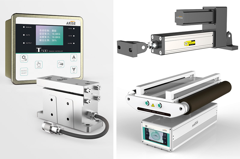
Web Tension Control Devices Of Web Guiding System
Because it ensures correct tension in the moving web throughout manufacturing operations, web tension control is an important aspect of a web guiding system.
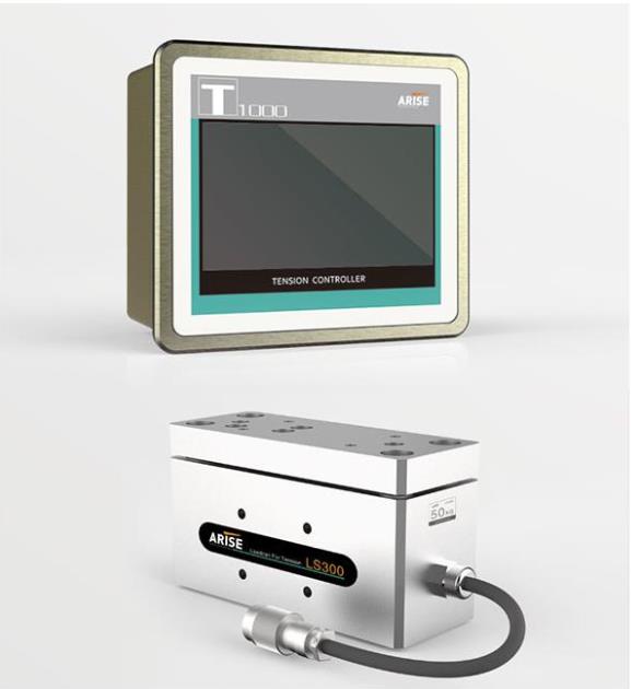
Load cells
Load cells are sensors that measure and quantify the force exerted to the web by the roller or other guiding devices. They convert tension force into an electrical signal that is used by the controller to control tension.
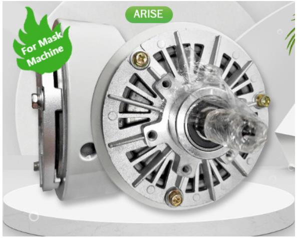
Brakes
Brakes are mechanical or electromagnetic devices that apply controlled resistance to the web, hence controlling tension. Magnetic powder brakes can be applied directly to the web or through a tension control mechanism like a dancer roller or a pneumatic brake.
Clutches
Clutches are mechanical devices that generate torque in order to manage web tension. By engaging and disengaging the web from the motor system, they allow for precise tension control.
Dancer rollers
Free-rotating rollers used to gather or release web tension are known as dancer rollers. They move up and down in reaction to web tension and give feedback to the controller, which modifies the tension.
Pneumatic or hydraulic cylinders
Pneumatic or hydraulic cylinders can be used to apply or release strain on the web by adjusting the position of the guiding devices or rollers. By manipulating them, the controller manages the tension in the web.
Inverters or drives
Inverters or drives regulate the speed of the motors that power the web guiding system. The tension in the web can be changed by modifying the motor speed.
Algorithms And Controllers For A Web Guidance System
PID controllers (Proportional-Integral-Derivative)
The web PID controller is commonly used to adjust web tension and position in web guiding systems. They compute the difference in web position or tension between the desired position or tension and the actual position or tension measured by the sensors. The controller then changes the guiding devices or rollers by providing control signals that provide proportional, integral, and derivative actions to rectify the error and maintain accurate web alignment.

PLC (Programmable Logic Controller)
Web guide controllers that take sensor inputs, execute control logic, and generate control signals for guiding devices or rollers are known as PLCs. PLCs are programmable and can be configured to perform a variety of control techniques, such as PID control, feed-forward control, and advanced control algorithms, based on the requirements of the production process.
Feed-forward control
The mechanism of feed-forward control prevents web misalignment by predicting changes in web tension or position based on known process factors. Feed-forward control algorithms predict web behavior using mathematical models or empirical data and provide appropriate control signals, improving system responsiveness and accuracy.
Adaptive control
Adaptive control is a control strategy that adapts control settings in response to changing process conditions in order to maintain optimal performance. Adaptive control algorithms update the control settings on a continual basis based on real-time sensor data, responding to changes in web properties, machine speed, and other process variables, ensuring perfect web directing even under changing conditions.
Fuzzy logic control
Fuzzy logic control is a type of control system that uses fuzzy logic to process sensor inputs and generate control signals. Fuzzy logic provides a mathematical foundation for dealing with uncertainty. Fuzzy logic controllers can deal with ambiguous or imprecise inputs and are useful in web guide systems where process variables are not well-defined or change over time.
Neural network control
Neural network control is a control method that uses artificial neural networks to process sensor inputs and generate control signals. Neural networks have the ability to learn from previous data and adapt to changing process conditions, making them ideal for sophisticated nonlinear and dynamic web guiding systems.
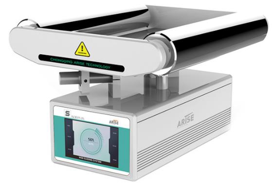
User Interface And Operator Controls Of Web Guiding System
The user interface and operator controls of a web guiding system are designed to make it easy for operators to interact with the system and monitor its performance.
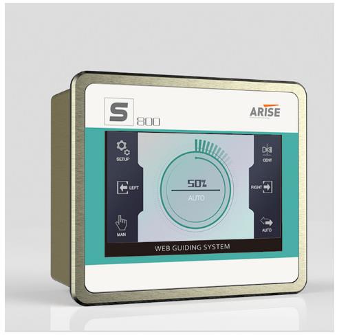
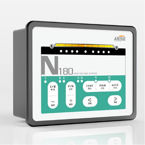
HMI (Human-Machine Interface)
The HMI is the graphical interface that allows operators to communicate with the web guidance system. It typically incorporates a touchscreen display that provides visual feedback on the condition of the system, such as web position, tension, and alarms. The HMI may also allow operators to alter control parameters and configure system settings, as well as set desired web position or tension.
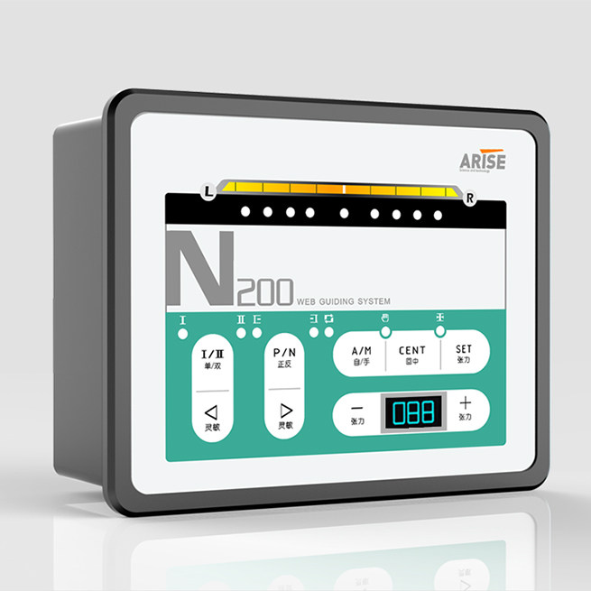
Control panel
The control panel is a physical interface that allows users to control the web guidance system through the use of buttons, switches, and knobs. It may provide options for adjusting the guiding devices or rollers, setting tension limits, starting system calibration, and conducting other manual control tasks.
Remote control
Some web guiding systems may additionally provide remote control, allowing operators to interact with the system via remote control devices or a remote access interface. Remote control makes it easier and more flexible to run the system from various locations inside the manufacturing environment.
Alarms and notifications
The user interface may incorporate alarms and notifications to alert operators to any flaws or abnormalities in the web guiding system, such as web misalignment, tension variances, or system malfunctions. Alarms and notifications can help operators identify and address problems quickly, allowing the system to run smoothly and effectively.
Data visualization and logging
The user interface may display visual representations of real-time and historical data, such as web location, tension, and other process factors. Data visualization can help system administrators monitor system performance, spot patterns, and make informed decisions. Data logging is another option that allows operators to examine historical data for troubleshooting, analysis, and process optimization.
System status and diagnostics
The user interface may display information about the system's health, communication status, and diagnostics. Indicators, status messages, and diagnostic tools can all be used to convey information to operators about the performance and health of the system.
Help and documentation
The user interface may also incorporate aid and documentation tools such as user manuals, online help, and troubleshooting guides to assist operators in effectively operating and maintaining the web guidance system.
Summary
The web guiding system's components work together to accurately align and steer online material during production operations, ensuring high-quality output and efficient operation.
In a web guiding system, PID control enhances precision, decreases variability, has a faster response time, and is adaptable to different web materials. We will introduce a web guide PID controller and explore its description, operating principle, benefits, applications, and difficults associated with its use in this part.
What is a Web Guide PID Controller
A web guide PID (Proportional-Integral-Derivative) controller is a closed-loop control system that uses sensor feedback to automatically change the location of a moving web material, such as paper, plastic, or fabric, to maintain it aligned with a desired route or edge. The web guide controller constantly monitors the position of the web material and calculates an error signal based on the difference between the desired and actual positions.
The PID controller then changes the output of an actuator, such as a motor or pneumatic cylinder, to correct the position of the web material. To change the output signal depending on the error signal, the rate of change of the error signal, and the integral of the error signal over time, the PID controller employs three control components.
How does a Web Guide PID Controller Work
The operating principle The web guide PID controller is concerned with maintaining the alignment of a moving web material.
The PID controller continuously monitors the position of the web material using one or more sensors. These sensors could be edge guide sensors, line sensors, or other sorts of sensors, depending on the application. Based on the difference between the actual position of the web material and a desired path or edge, the controller determines an error signal.
The PID controller then changes the output of an actuator, such as a motor or pneumatic cylinder, to correct the position of the web material. The actuator could be linked to a guiding roller, a steering roller, or another web handling system component, depending on the specific design.
The Proportional, Integral, and Derivative components of the PID controller are employed in that sequence to change the output signal based on the error signal, the rate of change of the error signal, and the integral of the error signal over time. This enables the controller to make precise and exact adjustments to the position of the web material.
In a web guiding system, the proportional component of the PID controller is typically used to respond quickly to changes in the position of the web material, while the integral component is used to eliminate steady-state errors and the derivative component is used to reduce overshoot and dampen the response to disturbances.
The tuning parameters of the PID controller can be modified to optimize its performance for different web materials, speeds, and other operating scenarios. Depending on the complexity of the web handling system, the web guide PID controller can be configured to operate in single-axis, dual-axis, or multi-axis control modes.

What are the Benefits of a Web Guide PID Controller
Improving accuracy and precision
The PID controller may precisely adjust the placement of the web material, improving the web handling system's accuracy and precision.
Reducing waste
By assuring proper alignment of the web material, the web guide controller helps prevent waste caused by misalignment, wrinkling, or other material faults.
Increasing productivity
The controller can keep the web material aligned at high speeds, boosting the efficiency of the web handling system.
Flexibility
Depending on the complexity of the web handling system, the PID controller can be configured to operate in single-axis, dual-axis, or multi-axis control modes. As a result, it is an adaptable solution for a wide range of web-handling applications.
Adaptability
The web guide controller can adapt to changes in the web handling system, such as differences in web speed, tension, or material characteristics, to ensure precise alignment of the web material.
Reduced operator intervention
The web guide PID controller may run autonomously, reducing the need for user participation and increasing system reliability.
What are the Applications of a Web Guide PID Controller
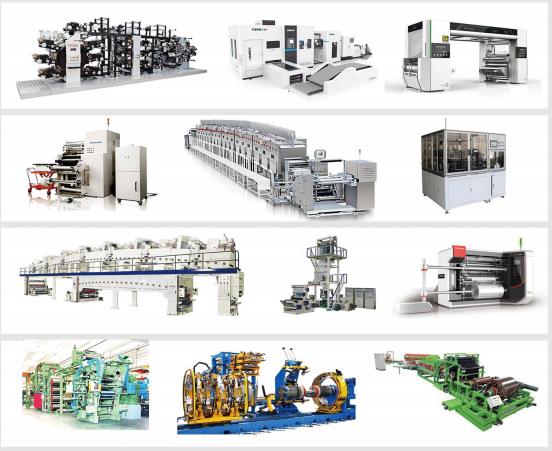
PID controllers for web guides are utilized in a variety of manufacturing and processing applications where precise control of web materials is required.
Printing
Web guides are used in printing applications. PID controllers are utilized to keep the web material aligned accurately during printing, decreasing waste and enhancing print quality.
Converting
Creating a Web Guide PID controllers are used in converting applications such as cutting or slitting of materials to ensure accurate web material alignment, reduce waste, and improve the quality of the converted output.
Packaging
Web guidelines for packaging are utilized in packaging applications. PID controllers are used to keep web material alignment correct during packaging operations, reducing waste and improving packaged product quality.
Coating
Web guide PID controllers are used in coating applications such as coating films or papers to keep the web material aligned, hence improving the quality of the coated result.
Textile
Web guide PID controllers are used in textile applications to maintain perfect fabric alignment during weaving or knitting operations, hence reducing wastage and improving quality.
Automotive
Web guide PID controllers are used in automotive manufacturing applications to keep materials perfectly aligned throughout processes such as cutting, stamping, or laminating, hence improving the quality of the manufactured automobile components.

What are in Difficults For a Web Guide PID Controller
Non-linear behavior of web materials
Web materials can exhibit non-linear behavior, making it challenging to forecast and control their position. This could induce oscillations or overrun in the control system.
Varying material properties
Thickness, elasticity, and surface characteristics of web materials may influence the behavior of the web handling system. This can make tweaking the PID controller for peak performance difficult.
External disturbances
External disturbances, such as changes in web tension or air drafts, may affect the position of the web material, resulting in mistakes in the control system.
Sensor positioning and precision
The accuracy and location of web guide sensors used to measure the position of the web material can have an effect on the operation of the control system. Inaccurate sensor readings can lead to incorrect control actions.
Maintenance and calibration
The PID controller and its supporting hardware components must be repaired and calibrated on a regular basis to ensure optimal operation. This may need downtime for the web handling system, affecting production timetables.
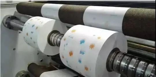
Web guide sensors are industrial devices that track the position of a moving web of material such as paper, film, or foil. They are frequently used in web-processing machines to keep the web centered and aligned during the manufacturing process.
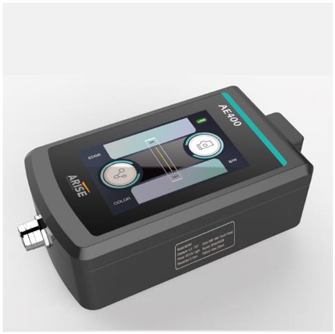
Operation Principle of Web Guide Sensors
Web guide sensors measure the lateral position of the web as it moves through a machine. Infrared edge sensors typically use an infrared light source and a receiver to detect the web's edge. The sensor continuously monitors the location of the edge as the web moves and sends a signal to the control system if any deviation from the desired position is detected.
Why The Web Guide Sensors Are Important In Various Industrial Applications
The control system receives data from the web guide sensors and adjusts the position of the actuator, causing the web to move into the appropriate position. They are critical in ensuring that industrial operations involving the movement of material webs are efficient, dependable, and create high-quality products.
Common Types Of The Web Guide Sensors
There are several different types of web guide sensors available on the market, each with its own strengths and weaknesses.
Ultrasonic sensors
Ultrasonic edge sensors use sound waves to identify the web's edge. Because they are unaffected by liquids or debris, they are especially useful in applications where the web may be damp or unclean.

Infrared Edge Sensor
The Infrared edge sensors are specifically intended to read the edge of webs with sound-transparent, thick weaves, and non-transparent properties. The light source for the web guide sensor is an infrared LED.

Sensors with capacitive coupling
They work by detecting capacitance changes caused by the web's presence. Because they are extremely sensitive and accurate, they are a popular choice for applications needing fine web alignment.
Optical sensors
Optical sensors detect the web's edge by using light. They are simple to install and use, and they have a wide range of uses.
Web Guide Sensors Are Integrated with A Web Guiding System
A web guide sensor is typically integrated into a web guiding system that also includes a control system and an actuator. It is a crucial component of a web navigation system. The sensor's output is used by the control system to alter the position of the actuator, which in turn moves the web into the necessary position.
Web guide sensors can help to decrease waste and improve overall efficiency while also improving web alignment. They can help to prevent faults like wrinkles or creases, which can lead to product waste or downtime, by keeping the web centered and aligned.
Summary
Web guide sensors are a must-have tool for any industrial application that involves the processing of moving material webs. Whether you're making paper, film, or foil, they can help you enhance product quality, reduce waste, and increase overall efficiency.
The coil industry is heavily reliant on web tension control, particularly for applications involving continuous webs or strips of materials such as paper, film, plastic, or metal. A web tension controller measures and controls the tension on the web during the manufacturing process. This method is critical for ensuring that the finished product meets the required specifications.
The Importance of Web Tension Controller in Coil Industry
Consistent Quality
Web tension must be maintained constantly for the production process to generate goods of consistently excellent quality. Any variations in web tension can cause faults or consistency concerns in the final product. For example, if the web tension is excessively high, the material may strain, resulting in a misshapen product. If the tension is too low, the material may wrinkle, resulting in defects.
Improved Productivity
Productivity can be increased by reducing waste during production with a web tension controller. With adequate tension control, the likelihood of faults can be reduced and the need for rework or scrap reduced. This could lead to higher yields and more efficient production.
Equipment Protection
A web tension controller may also help to prevent equipment damage. Web-handling equipment, such as spindles and rollers, can be destroyed if web tension is not properly handled. With effective tension control, the need for repairs or replacements can be reduced, and damage can be avoided.
Factors Affecting Web Tension Controller
Web Material
The web tension can be impacted by the kind and characteristics of the web material. The amount of tension necessary to maintain the correct web tension might vary depending on the elasticity, stiffness, and friction properties of the material being used.
Web Speed
The type and qualities of the web material can have an effect on the web tension. The amount of tension required to maintain adequate web tension may vary based on the material's elasticity, stiffness, and friction qualities.
Roll Diameter
The web tension may vary depending on the roll’s diameter. In order to maintain the desired tension, the web tension must increase as the roll diameter does.
Web Width
The web tension varies with the width of the web. Wider webs require more stress to maintain the desired tension.
How Web Tension Controllers Work
Using sensors, web tension controllers monitor the tension of the material as it passes through the manufacturing process. The web guide sensor delivers a signal to the controller, which compares the current tension to the target tension and makes necessary adjustments.
The tension can be varied by changing the web speed, adding tension with brakes or clutches, or changing the torque of the driving engine.
Web tension controllers normally use a closed-loop control method, which means the controller continuously checks the tension and makes real-time adjustments to maintain a consistent tension level. This contributes to the material being treated appropriately and to the desired quality standards.

Web Tension Controller Types
Closed-loop
Closed-loop controllers use feedback sensors to measure web tension and modify it as needed. The controller compares the present tension to the target tension and adjusts the brake or clutch to maintain it. Closed-loop controllers are incredibly accurate and can keep tension control exact even at high speeds.
Open-loop
To alter the tension of the brake or clutch, open-loop controllers use a set-point. However, they do not use feedback to adjust the tension. They are less accurate than closed-loop controllers and are often employed in applications where web tension requirements are less tight.Manual
Manual controllers are employed in applications where web tension is not crucial. These controllers employ a hand-operated brake or clutch to alter the tension. Although manual controllers are inexpensive, they are not suitable for high-speed or precision applications.
Benefits of Web Tension Controllers
1. Increasing Productivity
By reducing downtime and waste, web tension controllers can help to increase productivity. The process can run more smoothly and efficiently if the tension level is kept constant.
2.Improving Productivity
By ensuring that the finished product is built to the appropriate specifications, web tension controllers can help to improve its quality. This can reduce rejects while boosting customer satisfaction.
3.Cost Savings
Waste, downtime, and rejected products can all be reduced with web tension controllers. This can help to increase profitability while also cutting overall processing expenses.
4.Flexibility
Web tension controllers can be used with a variety of materials and processing conditions. As a result, they are very adaptable to a variety of manufacturing situations.
5.Safety
By minimizing the danger of accidents and injuries caused by manual tension management methods, web tension controllers can help to improve workplace safety.
Magnetic powder brakes are versatile devices that are commonly used in industrial applications requiring precise and smooth torque control. Printing, packaging, web tension control, and automotive are just a few of the industries that use them. In this post, we will look at the fundamental concepts, components, and benefits of magnetic powder brakes.
Working Principle Of Magnetic Powder Brake
A magnetic powder brake functions on the magnetorheology principle, which is the phenomenon in which the rheological properties of a material change in reaction to an applied magnetic field. The magnetic powder, which is a tiny particulate substance with magnetorheological behavior, is the most important component of a magnetic powder brake. Magnetic powder is often made up of microscopic magnetic particles spread in a non-magnetic carrier material.
A magnetic powder brake is composed of two principal components: a rotor and a stator. The rotor is connected to the input shaft and driven by the motor or another energy source, whilst the stator is connected to the output load. A coating of magnetic material exists between the rotor and the stator. When the brake is applied, the rotor and stator come into contact, and the magnetic powder is exposed to a magnetic field.
The magnetic field is created by an electromagnet mounted on the stator. A magnetic field penetrates the magnetic powder when an electric current travels through the coil. The powder solidifies and transmits torque between the rotor and stator because the magnetic particles in the powder align with the magnetic field. This allows for precise and smooth braking torque management.The torque level of the magnetic powder brake can be varied by varying the current supplied to the coil.
By varying the strength of the magnetic field, the rheological properties of the magnetic powder can be altered, resulting in varied levels of torque transmission. Magnetic powder brakes are ideal for applications requiring precise and smooth torque control because they enable for precise control of the braking torque.
Components of Magnetic Powder Brake
Rotor
The rotor is the input component of the brake, and it is connected to the motor or power source. When the brake is applied, a cylindrical or disc-shaped component usually rotates.
Stator
The brake's output component, the stator, is connected to the load. It is typically stationary and houses the coil or electromagnet that generates the magnetic field.
Magnetic Powder
The magnetic powder is used to transmit torque between the rotor and stator. It is composed of tiny magnetic particles suspended in a nonmagnetic carrier material such as oil or grease.
Coil or Electromagnet
The coil, also known as an electromagnet, generates the magnetic field that solidifies the magnetic material and transmits torque. It is typically mounted on the stator and is powered by an external source.
Advantages Of Magnetic Powder Brake
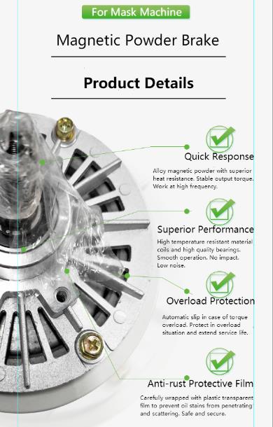
Smooth and precise torque control
By providing smooth and precise torque control, magnetic powder brakes provide accurate and consistent braking performance. The braking torque may be easily managed by varying the current supplied to the coil, allowing fine-grained control over the braking process. Precision speed and tension control is possible in printing, packing, and web tension management applications.
High accuracy and repeatability
Magnetic particle powder brakes are suited for applications that require precise and consistent braking performance due to their high torque control accuracy and repeatability. This is especially important in applications where the quality of the finished product is dependent on consistent tension management, such as printing, laminating, and coating.
Wide torque range
Depending on the size and design of the brake, magnetic powder brakes can function throughout a wide range of torque values, ranging from extremely low to very high torque levels. Because of their torque capacity versatility, they are suited for a wide range of applications, from small-scale to heavy-duty industrial processes.
Fast response time
Magnetic powder clutch brakes respond quickly, providing for fast braking torque engagement and disengagement. As a result, they are well suited for high-speed printing and packaging processes that require fast torque changes.
Overload protection
Magnetic powder brakes can protect driven equipment from overburdening. The magnetic powder brake slips when the torque exceeds the specified limit, preventing equipment damage and ensuring safety.
Noiseless operation
Magnetic powder brakes operate quietly, with no noise or vibrations, making them excellent for applications that require quiet operation, such as printing or packaging.
Compact and lightweight design
Magnetic powder clutch brakes feature a compact and lightweight design that allows them to be easily integrated into a variety of machine systems without adding unnecessary weight or space.
Customizable
The custom magnetic powder brakes can be applied to specific application needs, such as torque capability, response time, and mounting options. As a result, they are a versatile option for a variety of industrial applications.