A web guiding system is a mechanism used in many industries, including printing, packaging, and textiles, to offer accurate alignment and control of a moving web or continuous material during industrial processes.
Various sensors and detectors are used by the web guiding system to precisely determine the location and alignment of the web material being processed. These sensors and detectors play an important role in providing feedback to the control system, which then modifies the guiding mechanism to keep the web in the proper position.
Ultrasonic sensors
Ultrasonic web guide sensors use high-frequency sound vibrations to determine the position and distance of objects. They can determine the position of the web edge by creating ultrasonic waves and monitoring how long it takes the waves to bounce back after impacting the web substance. Ultrasonic sensors are often used in edge guiding systems to enable precise and non-contact web edge detection.
Vision sensors
Using cameras and image processing algorithms, vision sensors photograph online content and analyse its placement and alignment. They can detect web elements such as edges, lines, and patterns and send real-time data to the control system for web directing changes. Vision sensors are incredibly versatile, and they can be used in edge, centre, and combination guiding systems.
Infrared sensors
Using infrared light, the infrared web guide sensor detects the presence and position of things. They can be employed in web guiding systems to identify the web edge by emitting infrared light and measuring the light's reflection or transmission when it comes into contact with web material. Infrared sensors are useful in applications where the web material is transparent or translucent, such as in the plastic film and glass industries.

Capacitive sensors
Capacitive sensors work by detecting changes in capacitance caused by the proximity of objects. They can determine the position of the web material by measuring capacitance changes when it comes into touch with the sensor. Capacitive sensors are commonly used in centre guiding systems to detect the position of the web material in relation to the centerline.
Laser sensors
Laser sensors use laser beams to measure distances and positions precisely. They can be employed in web guiding systems to precisely establish the position of the web edge by emitting laser beams and detecting the beams' reflection or scattering from the web substance. Laser sensors are suited for applications that require high precision and resolution.
Load cells
Load cells are used to calculate the tension or stress on a web material. By placing them in the web route, they can supply input to the control system for tension control and web guiding modifications. To keep the web material tensioned and aligned, load cells are frequently used in web tension control devices such as brakes and clutches.
Types Of Web Guiding System
Edge Guiding
Edge guiding is the most common type of web guiding mechanism, in which the web edge guiding system modifies the location of the web material based on the detection of one or both web edges. Edge guiding systems detect the position of the web edge(s) and make adjustments to keep the web aligned along the desired path. Edge guiding systems can contain actuators such as steering rollers or guide rails to physically move the web material to the desired place.
Center Guiding
The technique of sensing the position of the web material's centerline and altering the guiding mechanism is known as centre guiding, also known as line guiding or line following. In centre guiding systems, sensors or detectors are often employed to measure the location of the web material in relation to the centerline and then make adjustments to keep the web aligned along the centerline. Centre guiding systems might contain actuators such as center-driven rollers or adjustable guide bars to centre the web material.
Role Of Actuators In The Web Guiding System
Web guide actuators are important components of a web guiding system because they physically change the position of the web material in response to data from sensors or detectors. Actuators are devices that convert electrical, hydraulic, or pneumatic signals from the control system into mechanical motion in order to move or control the position of the web material.

Steering Rollers
Steering rollers, also known as dancer rollers or idler rollers, are commonly used in edge guiding systems. They are supported by adjustable arms or brackets that can be moved horizontally or vertically to guide the web material. The position of the steering rollers is changed based on feedback from sensors or detectors to keep the web material in the appropriate area.
Guide Rails
Guide rails are solid structures or bars put parallel to the web route in edge guiding systems. They can be changed horizontally or vertically to direct the web information. The location of the guide rails is adjusted based on feedback from sensors or detectors to keep the web material aligned along the desired path.
Center-Driven Rollers
Center-driven rollers are used in centre guiding systems to direct the web material down the centerline. They are powered by a motor and can be adjusted horizontally based on sensor or detector feedback to centre the web material. The speed of the center-driven rollers is controlled by the control system in order to maintain proper web material alignment.
Adjustable Guide Bars
Adjustable guide bars are used in centre guiding systems to guide the web material along the centerline. They are stiff bars that can be adjusted horizontally or vertically based on sensor or detector data to centre the web material. Adjustable guide bars are typically installed on both sides of the web material and can be altered independently to maintain proper alignment.
Pneumatic or Hydraulic Actuators
Pneumatic or hydraulic actuators are utilised in web guiding system to provide accurate and strong control of the web material. Using pressurised air or hydraulic pressure, they generate mechanical motion and change the location of the web material. Pneumatic or hydraulic actuators can be used in conjunction with other types of actuators, such as steering rollers or guide rails, to achieve the desired guiding performance.
Many factors influence the tension control system, which can lead to related issues. According to the structure and working principle of the tension control system, analysing and determining the reasons, and correcting problems with appropriate techniques to ensure the tension control system's stable operation. This article discusses three typical faults and their solutions of tension control system.
1. Inaccurate Overprinting Of Tension Control System
Fault phenomenon
During normal printing operations, the swing roller swings erratically and has a considerable swing amplitude, resulting in inaccurate overprinting.
Solutions
Because the construction of the tension control system is quite complex, there are numerous explanations for this failure, which are summarised below.
(1) The swing roller cylinder's pneumatic control circuit components are prone to deterioration, resulting in piston leakage and unstable swing roller cylinder loading pressure. In this regard, it is possible to consider replacing damaged pneumatic circuit components, as well as replacing the swing roller cylinder if necessary.
(2) The high-precision potentiometer runs for a long time within a specific range, and when the resistance value within that range varies, it is easy for the high-precision potentiometer's feedback signal to become unstable. At this point, the high-precision potentiometer should be replaced as soon as possible.
(3) There is an excessive gap between the potentiometer gear and the rotary shaft gear. The position of the swing roller will shift as the tension changes. However, because of the gap, it is easy for the swing roller to repeatedly swing back and forth, reducing printing accuracy. The clearance should be modified in accordance with guidelines for this.

2. Unstable Tension Of Tension Control System
Fault phenomenon
When the winding diameter is big during the winding process, the winding tension display value frequently drops as the winding diameter grows. At this point, the driver's output current will continue to rise. When the output current exceeds the motor's rated current, the driver will activate overcurrent protection and send a fault alarm.
Solutions
First, ensure that the load on the driver and the motor speed encoder are both normal. Following calibration of the winding web tension controller, it was discovered that one of the tension sensors had failed, causing the detected winding tension signal value to be half of the real winding tension value. To achieve the predetermined winding tension, the web tension controller will constantly raise the output until it reaches 100% as the winding diameter grows. The actual winding tension has significantly exceeded the predetermined winding tension at this point, and the reel material is extremely tight. As the load grows, the drive overcurrent protection kicks in. After replacing the tension sensor and recalibrating, the system returns to normal. It should be noted that when calibrating the winding tension controller, the weight used should be as close to the full tension value as possible to improve the tension control accuracy.

3. Excessive Winding Starting Tension Of Tension Control System
Fault phenomenon
When the tension control system starts, the full tension value of the winding tension controller is exceeded, and the equipment must run for approximately 2 minutes to establish constant tension functioning. This not only wastes a considerable amount of raw materials, lowering yield, but it also readily causes zero displacements of the tension sensor, resulting in tension control value deviation.
Solutions
Adjust the driver's input signal, as well as the gain, bias, and PID parameters of the tension feedback signal, but the fault persists. Check to see if the tension reset and tension sensor signals are normal. When the take-up tension controller was detected, it was discovered that its internal stall storage reset point was broken, despite the fact that the external reset signal of the take-up tension controller was normal. In fact, the take-up tension controller not only did not reset but also saved the previous roll's take-up tension value, resulting in a significant take-up starting tension problem. The winding beginning tension will revert to normal after repairing the internal stall storage reset point of the winding tension controller and replacing damaged parts.
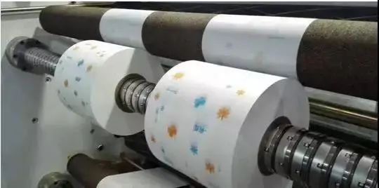
In the process of winding or unwinding, the quality and efficiency of production should be guaranteed. Tension control is very important. If the tension is too small, the coil is easy to loosen and causes lateral drift. If the tension is too large, the surface of the coiled material will wrinkle or even break.
Functions Of Tension Control
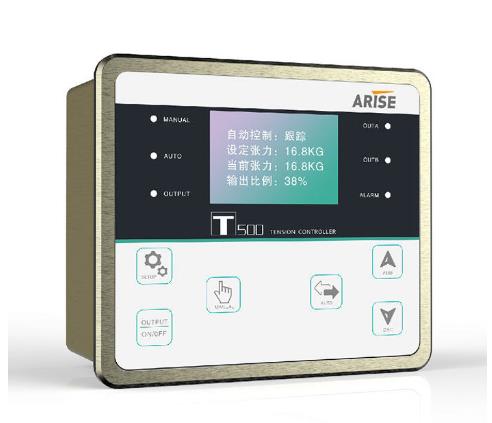
The tension controller directly affects the product quality. The tension control system is one of the core elements of the printing machine. Its performance reflects the performance of the gravure press. The tension control system plays the following roles.

1. According to the change law of tension, control the uncoiling speed of coil.
2. According to the direction of overprinting error, change the local tension in printing to achieve higher overprinting accuracy.
3. Adjust the speed of the winding shaft to make the winding neat.
4. Eliminate the tension fluctuation caused by the film itself.
5. Control and adjust the motion speed of the film.
Factors Affecting Tension Control
During the printing process, the tension of the film roll is constantly changing during the movement, which is mainly caused by the following factors
1. In the process of winding and unwinding, the diameter of the unwinding and rewinding is variable, and the change of the diameter will cause the change of the coil tension.
2. The shape of the membrane roll is not a standard cylinder, with a certain degree of eccentricity and local deformation. The weight of the coil is inconsistent.
3. The thickness of the film is uneven.
4. There are pressure differences and diameter differences between each roller, and the tension between each printing unit is inconsistent.
5. When the operating state of the printing machine changes, such as the increasing speed, decelerating speed, start, brake, and roll change, the tension changes greatly.
6. The change of the lifting speed of the machine will inevitably cause the change of the tension of the whole machine.7. In the process of rewinding and unwinding, the diameter of winding and unwinding is constantly changing, and the change of diameter will inevitably cause the change of raw material tension. Under the condition that the braking torque of unwinding is constant, the diameter decreases and the tension increases. On the contrary, if the winding torque is constant, the tension will decrease as the winding diameter increases.
8. The change of the tightness of the raw material roll will also affect tension control of the whole machine.
9. Non-uniformity of printing raw materials
For example, the fluctuation of material elasticity, the change of material thickness along the width and length direction, the mass eccentricity of the coil, and the change of production environment temperature and humidity will also affect the tension control of the whole machine.
10. The change of speed during printing affects the tension control. When the running speed is increased or decreased, the main motor speed changes. First of all, it causes the instantaneous change of the tension of the material from the unwinding traction to the rewinding section, and the tension must be stabilized gradually after a period of small vibration of the material.
The methods of tension control
The tension control methods are generally divided into manual control and automatic control, and automatic control can be divided into constant tension control and taper tension control.In terms of automatic tension controller, it includes open-loop semi-automatic tension controller and closed-loop full-automatic tension controller. The open-loop semi-automatic tension controller adjusts the coil tension by detecting the change of coil diameter, that is, taper tension control.
The full-automatic tension controller directly detects the tension of the coil through the tension sensor or tension detector and feeds back to the controller. The controller adjusts the output according to the detection signal to ensure the constant tension of the coil.
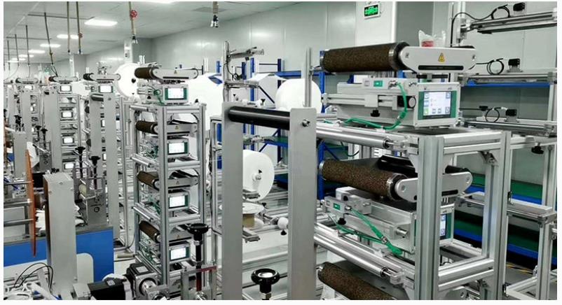
The tension control system plays a very important role in the production of coil materials, such as high-speed gravure printing machine, laminating machine, coating machine, slitting machine and other equipment, are basically equipped with advanced tension control system, which mainly controls the tension of paper, plastic film and other reel materials. The tension control plays an important role in keeping the tension constant. In the production process, if the tension is too large, it will lead to tensile deformation of the material. If the tension is too small, the stress deformation between the material layers will easily occur, resulting in irregular winding, which will have a direct impact on the quality of the final product.
In order to ensure the smooth operation of the tension control system and maintain the optimal tension of the coil material, it is necessary to fully understand the tension control system. This article mainly tells the control modes, composition and working principle of the tension control system.
Control Modes Of Tension Control System
The main control modes of tension control system include direct tension control and indirect tension control.
Direct tension control is also called feedback control. It adopts tension sensor to detect the actual tension, and then converts the measured value into feedback signal and compares it with the preset tension. When there is a deviation between the two, the tension controller gives the corresponding control of the tension control system to match the actual tension with the preset tension, thus forming a tension closed-loop system. Direct tension control does not need to consider various adjustments and compensations, and can eliminate steady-state errors with high control accuracy.
Indirect tension control, also known as compensation control, can adjust and compensate the parameters that affect the tension stability to avoid the tension changes that will occur and indirectly maintain the tension stability. Compared with direct tension control, indirect tension control has poor randomness and low control accuracy.
Structure And Working Principle Of Tension Control System
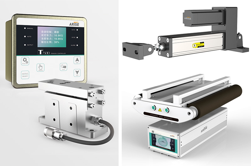
The tension control system is mainly composed of three parts, which includes unwinding tension control system, traction tension control system and winding tension control system. The constant tension control of the coil material is realized through tension sensor, tension controller, frequency conversion controller, magnetic powder brake and other components.
1. Unwinding tension control system
Working principle
The tension sensor detects the actual value of the unwinding tension and feeds it back to the tension controller. Compared with the preset value of the unwinding tension in the tension controller, the deviation between the two is calculated by PID and the control voltage is output to control the resistance moment of the magnetic powder brake acting on the unwinding shaft, so as to achieve the purpose of adjusting the unwinding tension.
2. Traction tension control system
Working principle
In the production process, when the traction tension of the coil material changes, the swing roller will make corresponding swing amount. At this time, the high-precision potentiometer will indirectly measure the change of the traction tension, and then feed back the corresponding signal to the traction roller driver. After the PID adjustment, the operation speed of the traction roller will be controlled. The swing amount of the swing roller will be adjusted by changing the pressure of the low-friction cylinder to keep it stable at the set position, that is, the traction tension control will be realized.
3.Winding tension control system
Working principle
The tension control system detects the actual value of the winding tension through the tension sensor, and then feeds it back to the winding web tension controller. Compared with the preset value, the deviation between the two is calculated by PID and the control voltage is output to the winding motor driver to adjust the running speed of the winding motor to achieve constant tension control. In the winding tension control system of some equipment, the taper tension control system is often added, which can make the coil material in the state of tight inside and loose outside during the winding process, so as to prevent the slipping among layers of the coil materials and improve the tension stability of the subsequent procedures.
Tension control refers to the ability to control the tension of raw materials when they are transported on the equipment. The tension control of slitting machine must be effective for any running speed, including the acceleration speed, deceleration speed and uniform speed of the machine. Even in case of emergency shutdown, it shall be able to ensure that the cut raw materials are not scratched or damaged.
Why Tension Control Is ImportantIn The Slitting Machine
With the increasing degree of mechanization, the requirements for the efficiency of winding operation are also higher and higher. When the slitting machine is applied to the slitting operation of film, tape and paper, the large reel of the whole roll can be divided into several small reels according to different requirements to meet the needs of different occasions. The tension control system is the core part of the slitting machine.
The tension control of the slitting machine is basically manual tension control and automatic tension control. Manual tension control is to control the tension by adjusting the manual power supply device by the operator when the coil diameter changes to a certain stage during the winding or unwinding process.
Full-automatic tension control is to measure the actual tension value of the material belt directly by the tension sensor, and then convert the tension data into a tension signal and feed it back to the tension controller. By comparing this signal with the preset tension value of the controller, the control signal is calculated. The automatic control execution unit makes the actual tension value equal to the preset tension value, so as to achieve the purpose of stabilizing the tension.
The stability of tension control is directly related to the quality of slitting products. If the tension is insufficient, the raw material will loose or drift during operation, and the finished material will wrinkle after slitting and rewinding. If the tension is too large, the raw material is easy to be broken, resulting in more broken ends of the finished material after slitting and rewinding.
Tension Control Of The Slitting Machine
The formation of tension can be realized in many ways, but its basic principles are consistent. During the startup process, the linear speed of the winding coil is greater than the linear speed of the unwinding coil to generate a certain tension in the winding roll. When the winding reaches the appropriate tension required by us, timely adjust the power mechanism to stabilize the linear speed of the winding coil and the unwinding coil, so that the raw material can operate stably under this tension. The tension control system is to meet the tension stability of the whole machine.
Tension Control Detection System Of The Slitting Machine
1. Tension sensor detection
It is a direct detection of tension, which is closely combined with machinery, and is equipped with a detection method of moving parts. Usually two sensors are used in pairs, and they are installed on the end shafts on both sides of the detection guide roller. By detecting the applied load on both sides of the guide roller, the material belt makes the tension sensor sensitive element produce displacement or deformation, thus detecting the actual tension value, converting this tension data into a tension signal to feed back to the tension controller.
2. Indirect tension detection system of floating roll
A set of floating roll is installed in front of the tracking roll. The position of the floating roll is detected by a potentiometer. The tension control method is to maintain the constant tension by maintaining the position of the floating roll unchanged.
3. Magnetic particle clutch
Magnetic particle clutch is used to control the rotational torque of the input take-up roll to achieve tension control: the magnetic particle clutch is composed of the driving part and the driven part, and is connected with the take-up roll through the universal coupling and other transmission mechanisms, and the middle is filled with fine iron particles as the torque transmission medium.
A magnetic field is formed by applying a certain current to the excitation coil, and the magnetic particle is magnetized. The magnetized magnetic particles attract each other and form a chain arrangement. When the driving part rotates at a constant speed, the coupling force between the magnetic particles is destroyed and a circumferential tangential force is formed. The product of the tangential force and the radius of the magnetic particle circle is the rotational torque of the driven part for winding up, so as to realize the coupling of the output torque from the driving part to the driven part in continuous rotation, thus achieving the purpose of tension control.
4. The slitting & unwinding capacity and speed tension detection system
It mainly uses magnetic particle brake to control the unwinding speed. Its working principle is that the magnetic particle brake is equipped with a coupling, as well as input parts and output parts with magnetic coils. Below the magnetic coil is an annular groove, and below the groove is an annular rotor, namely the output part. The annular groove is located in the center of the output part, and the groove is filled with magnetic powder.
When there is excitation current in the magnetic coil, the coil will generate magnetic flux to make the magnetic particles arranged along the magnetic field direction, which will generate damping between the input part and the output part and transfer the torque. If the tension and speed applied on the aluminum foil are increased or decreased, the tension and speed can be effectively controlled by changing the magnitude of the excitation current, or the current or voltage value applied by the amplifier to the coupling coil.