
An anchor is a vital part of the boat and is one of the most widely used items in the marine industry.”. The anchor is used to protect your boat. It is synonymous with durability and resistance to bursting. The type of bottom—mud, grass, sand or rock—will dictate different choices of anchors, as will the size and windage of the marine, the wind conditions and the sea state When choosing an anchor for your boat, it is paramount to consider both your length of the boat, the weight of boat and weather conditions in your area.
Which style or category of anchor?
Choose between the two most common anchor styles, the fluke and the plow, or if you are marineing in a small marine, on protected inland waters, the inland type.
The most popular type of anchor is the fluke anchor, also called the Lightweight or Danforth anchor, which includes the West Marine Traditional and Performance2 anchors and is often the only anchor on many smaller marines. Light and easy to weigh, it stows flat and holds well in mud or sand. Its excellent holding power-to-weight ratio means you can use a lighter anchor compared to other types, but it doesn’t hold well in grassy or rocky surfaces. Its flukes and stock (the wide crossbar at the top) are more prone to foul on rocks or the anchor rode.
Plow and Scoop anchors—the “single point” style represented by the Manson Supreme, Rocna, CQR, Delta and Claw—have the best all-around holding ability in varying bottom conditions. They generally reset themselves easily if the wind or current changes direction. The newest “scoop” designs, like the Manson and Rocna anchors, include round “roll bars” that self-right the anchor, automatically turning it right side up.
Plow/scoop anchors hold more effectively in grass, mud and sand. They do not have projecting flukes that foul easily, but their shape makes stowing them more awkward (a bow-roller or bowsprit is the best solution). Heavier powermarines and cruising sailmarines often use plows as primary anchors.
For the greatest anchoring security, you should carry two anchors of different styles, one each of the Danforth style and the plow/scoop variety. The type of bottom—mud, grass, sand or rock—will dictate different choices of anchors, as will the size and windage of the marine, the wind conditions and the sea state. Some anchoring situations also call for more than one anchor to be used simultaneously.
YSmarines is one of the leading marine anchor suppliers with high performance, beautiful design with various colors and maximum protection for boats, which can provide the anchor in a wide variety of types to meet customer's requirements.

Tool cabinet is used for the setting management of tools, tools and parts in the production site, so that the goods and access work can truly be punctual, accurate, high efficiency and low consumption. Sanji-first is one of the leading tool cabinet manufacturers and the products are widely used in modern enterprises. The tool cabinet is used in factories, workshops, auto repair shops, 4S stores, auto parts stores, technical training workshops, units, schools, maintenance workshops and other occasions.
Features of tool cabinet:
1. High strength structural design and special spray surface treatment process can adapt to the complex working environment of the factory.
2. Guide rail with high quality bearing to ensure that the single drawer can easily and smoothly under the load rated load.
3. The partition of free adjustment in the drawer allows you to separate the storage space.
4. Wide - wide aluminum alloy drawer handles and replaceable labels, beautiful, convenient and practical.
5. Advanced drawer safety button design ensures that drawers will not slip out accidentally after closing.
6. Equipped with safe baffle design, ensure that the drawer opens and 100 % will not drop.
7. Adopt the international advanced level lock, the lock is advanced, only one key can lock all drawers, ensure the safety of the goods.
8. Free choice of drawers with different heights to meet customers' needs.
9. The bottom pads of the cabinet shall protect the cabinet from damage when placed or moved.
10. Multiple surface colors to meet the requirements of the overall layout of users.
11. Choose the drawers with different height according to the requirements, and fully meet the needs of the production site.Tool cabinet classification:
Use site classification
Factory workshop tool cabinet
School special tool cabinet
Household tool cabinet
By capacity classification
Light tool cabinet
Medium tool cabinet
Divide by drawer
Single guide drawer, drawer cannot pull out all. (similar to a more closet in the home, just a bigger load)
Double guide drawer cabinet, that is to have fixed orbit and moving rail to cooperate with each other, drawer can pull out all.

How to select tool cabinet
Tool cabinet selection according to the demand structure, try to be efficient, low consumption, the heaviest is convenient, affordable, meet their actual needs is the best choice. Therefore, the tool cabinet is more customized products.
Here are some suggestions for the selection of tool cabinets.
A, castor
Devices move castor depend on the type of tool cabinets, light tool cabinet is best can install castor, convenient moving and handling, and heavy tool ark by comparison of the province, and depositing of heavy, caster and easy to wear, and objects too heavy to move up and not too safe.
B, the guide rail
The guide rail of tool cabinet can be divided into single guide rail and double guide rail. Single guide rail is suitable for light tool cabinet, while double guide rail is applicable to heavy tool cabinet. Then, the weight of the general light tool cabinet is between 60 and 80 kg. If the weight is high, double guide rail should be used in 150-200kg, because the double guide rail cabinet can carry up to 250kg.

C, armrest
Tool cabinet whether need device armrest, when used in tool ark to see whether the user workshop need regular mobile, if needed, and tool cabinet storage is a bigger item weight, easy installation on the armrest can workers, and is easy to use.
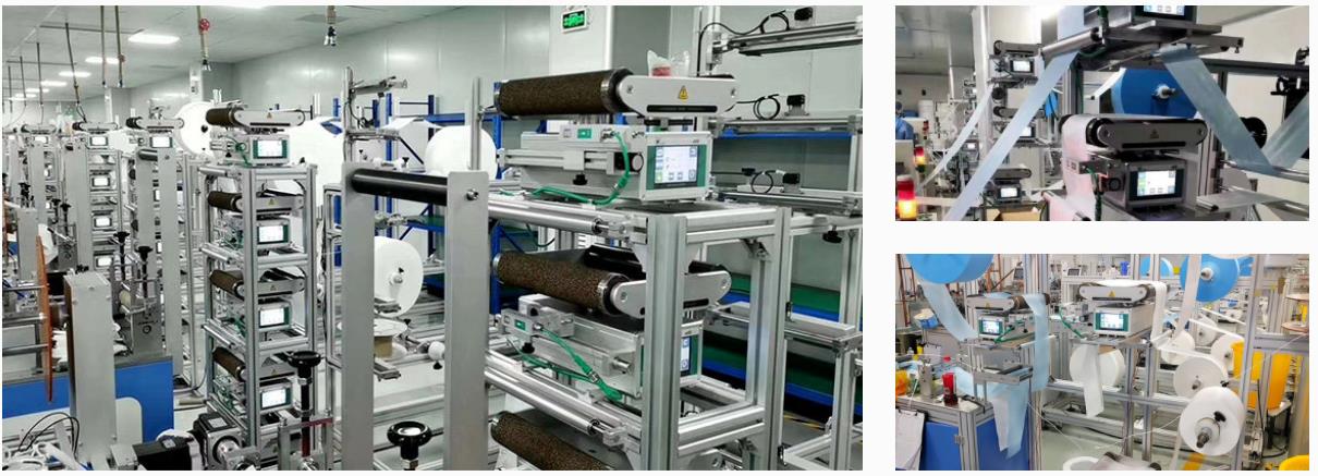
Arise all-in-one web guiding system can achieve multi-layer material alignment and there is no waste in the refueling process. The web guide system is an edge position controller for tracking the edge of the coil materials or printing lines for high-accuracy differential and swing. It is composed of large-scale industrial integrated circuits and has the advantages of high reliability and long service life.

Here are a few tips to operate the web guiding system after installation
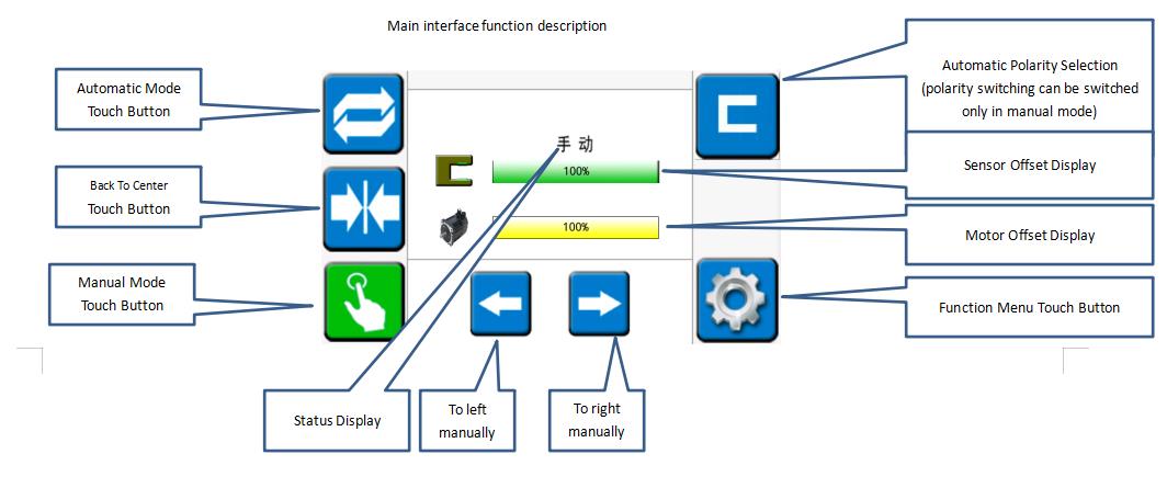
Operation of the main interface
1. Install the rack and the all-in-one machine, plug the power and sensor plugs of the all-in-one into the corresponding sockets, and power on.
2. Enters the "manual" mode of the main interface and touch the "function menu" button. Then touch the "self-learning" button to enter the all-in-one self-adaptation and automatically return to "manual" mode.
3. Touch the "back to center" button, and then touch the "manual" button, respectively pressing the material of the same layer into the material according to the "material penetration diagram". Run the main machine for a few minutes to move the material for a period of time.
4. In the "manual" mode, adjust the sensor's position and the moving bracket in a large range and then adjust the rotary knob in a small range. (Adjust the position to the sensor offset display about 50%)
5. In the "automatic" mode, adjust the edges of the other layers of materials to coincide with the edges of the reference based on one layer, and the correction and debugging are completed.
Infrared sensor calibration
For some materials that are not easy to identify, the infrared sensor is required to achieve the best web guide effect.
Steps
1. Long press the "SET" button to make the sensor light flash (release the button after flashing)
2. Tighten the material and put it into the position of the sensor near the light lens (the material will completely cover the circular light-transmitting sheet). Then wait for 3 seconds and remove all the materials from the sensor.
3.Press the "SET" button until the light does not flash, and then release the button. The process of the calibration has been completed.

Common problems in the operation of the web guide system
1. The machine will swing to the limit alarm when it is switched to the "automatic" mode. (Confirm whether the correction polarity is correct and whether the sensor has a signal)
2. The speeds of the left and right swing are inconsistent in the "automatic" mode. (Check if the infrared sensor changes range from 0-100%)
3. When there are different materials in the "automatic" mode and the integrated machine does not swing, the infrared sensor is needed to calibrate the material.
If you have any question about the operation, please contact Arise web guiding.
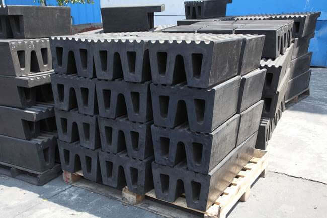
Rubber fenders are developed in a wide range of variations to serve different applications. Rubber Fenders decrease the input reaction force and provide requisite angular guidance to the hull pressure. These are the fenders which have the highest market demand. These fenders also have a positive impact on rubber industries round the globe. There noticed a great advancement and growth of the rubber industry due to marine application of rubber in last ten years. There are many types of marine rubber fenders, manufactured by different shipping accessory companies, which are detailed as follows:
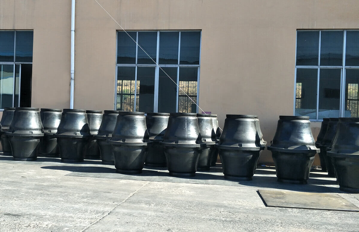
Super Cone Fenders: These are the latest sort of rubber fenders and generally referred as “Cone Fenders”. The conical body of the cone fenders keeps them stabilised at even higher values of compression angles. They are highly efficient and provide optimum performance. They have better resistance to shear and over-compression. Their geometry plays a significant role in their stability. Today, rubber compounds find their widespread application in marine industry and extensively used for the manufacturing of Cone Fenders.
Cylindrical Fenders:They are the most basic and common fender systems used in today’s times. They can be used for all types of marine marines and ships and they are quite economical too when the aspect of fitting them up is taken into account.
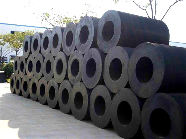
These are easy to install, widely used fenders with simpler design. They can serve to both large as well as small vessels. As per the requirement of cylindrical fenders, these are available in three size categories: Small Cylindrical Fenders, Intermediate Cylindrical Fenders and Large Cylindrical Fenders. These fenders are economical and have thick walls which can efficiently resist wear, abrasion and higher loads.
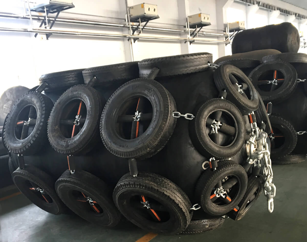
Pneumatic Fenders: pneumatic fenders are the ideal choice for inter ship dealings and port accessories. Their deployment is quick and robust. At the time of docking the pneumatic fenders minimize the risk of damage and safeguards both people and cargo. These fenders should comply with quality assurance guidelines of ISO issued in 2014. These are of five types namely: chain-tire net (CTN) pneumatic fenders; Sling type fenders; low-pressure pneumatic fenders; hydo-pneumatic fenders and. The CTN pneumatic fender has a network of tyres connected with chains in horizontal as well as vertical directions to protect the fender body. As the chains remains in water all the time so must be made up of corrosion-resistant galvanized materials. These are the simplest and cheaper types of marine rubber fenders which increases the clearance between the structure and the hull to a larger extent. Sling type pneumatic fenders are similar to chain type fenders with the only difference that fenders can be slung with even ropes made up of meshed wire strands than chains. Low pressure pneumatic fenders are the type of pneumatic fenders which deliver minimum pressure to the hull by absorbing kinetic energy to a maximum extent by providing maximum contact surface. Hydro-pneumatic Fenders: These are the pneumatic fenders which are made in compliance to the need of fender.
W Fenders: W fenders are used mainly to aid the larger ships and marines because they offer a high rate of resistance and thus better protection to the water-crafts in case of any accident occurring.
These marine rubber fenders should be capable of serving to all their commitments in all environmental conditions. The marine rubber fenders should be durable and they are designed to serve a longer period of time. So durability and strength are the main factors for selection of any kind of fender.
A variably baggy or cambered web will cause the web to track toward the variably tighter side. Variabilities in roller traction or drag can cause a steering of the web. Changes in tension will cause changes in how straight the web travels downstream. At zero tension, edge position control is essentially lost. However, there are other edge movement factors which include nip roller draw variations, aerodynamics and so on. Web guides are used to bring the edge or center of a web to a specific CD position. The guide location may be at an unwind to get the web started down through a machine in a consistent position, at an intermediate location, or at the winder to improve roll edge quality. The accuracy demands for the guide may vary from merely keeping the web on the rollers, to minimizing trim loss, to registering several print colors to within a couple of mils. Guides may be either active or passive.
What is an acceleration offset
One of the most troublesome of the edge position excursions is known variously as the acceleration or ramp offset. Here, the web moves sideways when machine speed is increased or decreased. Usually the rate of movement is most severe at the top and bottom of the speed change rather than on the speed ramp itself. Unfortunately, the term “acceleration offset” belies the true nature of the cause of the edge movement. Indeed, the web does not even know how fast it is moving.
In the case of absolute traction, the web will conform to the Normal Entry law on all rollers, including the one that is misaligned. Note how the web moves over as the result of this misalignment. In the case of pure flotation, however, the web is not steered by the ‘roller’ and, thus, passes straight through the machine. The case of sliding is intermediate in that there is a small offsetting of the web.
Thus, every roller or element that touches the web also steers the web. However, if the roller is stationary and the state of traction constant, the path of the web will remain constant. That is not to imply straight. Obviously the web will snake through the machine in conformance to web handling laws.
However, if the web changes from full to partial tracking the path of the web will change slightly in response. This change in traction will be subtle and not easily picked up by conventional observations and measurements. Nonetheless, it will cause the web to move in response.
While there are many ways the state of traction can change, the most common is due to a tension change on a lightly wrapped roller. This means that if our drive allows tension variations, the web might shift slightly on some of the rollers. Furthermore, the condition which is most difficult to hold tensions is during a speed change.
Thus, as we not see, the acceleration offset is not due to the speed or speed change itself, but rather due to tension variations that can and will accompany the speed change. Our first efforts should then be to tune the drive so that tension is held well at sensors (load cells) as well as elsewhere where there are no sensors. Sometimes tension is held well only at the drive points or sensors, but not elsewhere because the web might be pulling against excessive roller inertia or drag.
However, we can also expect to reduce the severity of the offset if we reduce roller misalignment or other geometrical problems. The surest way to do this is through optical alignment of every roller in the line because even the lowly idler is as capable of shifting the web as any of the major process rollers. However, sometimes it is not the roller, but rather an air float oven, that is steering the web.
If you want to keep your web as uniform, flat, and baggy free as possible. This is because the web with profile troubles will merely exaggerate the difficulties discussed here. Only when material and machine are made true will edges run consistently.
How does the web guide system work?
The active web guide system is composed of a sensor, an actuator, and a controller, which is a high-efficiency edge position control. The sensor can be any detector which can reliably pick up the edges of a web. The most common are pneumatic (nonporous webs), photoelectric (opaque webs), or paddies (thick webs). The web must be flat (free of curl) and stable (free of flutter) through the edge sensor. For this and other reasons, the sensor is often placed near a roller. If two sensors are used, the web could be guided to the front edge, back edge, or center.

The output of the sensor goes to a controller which outputs a movement command to the actuator. If the gain of the controller is too low, the response of the guide will be sluggish and slow to correct. If the gain of the controller is too high, the guide will be hot but overshoot, or may even be unstable. The actuator which moves the guide mechanism may be a stepper motor and ballscrew for smaller assemblies or a hydraulic cylinder for larger assembli`es. The actuator and framework must be stiff for responsive operation.
For more professional knowledge, please visit the page of web guide system articles.