A viscometer refers to an instrument used to measure the viscosity of fluids. Viscometers can more accurately control the viscosity of measured substances, so they are widely used in the manufacturing process of liquid and gas products. But many people may have only heard of viscometers, but they don’t know what specific classifications of viscometers are, and what are the functions of different classifications of digital viscometers. This article will introduce the classification andt he functions of different types of digital viscometers. I hope it can help you.
Digital viscometer classification
The most commonly used digital viscometers in the production process are rotary, ultrasonic viscometers, and capillary viscometers.
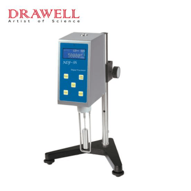
Rotational viscometer
a digital viscometer with a rotating measurement system. There are many kinds of it: according to the measurement parameters, it can be divided into measuring torque type (rotation speed constant) and measuring speed type (torque constant); according to the different structures of the device, it can be divided into coaxial cylinder type and cone-plate type. For a torque-measuring viscometer with a coaxial cylinder structure, when the outer cylinder rotates at a certain speed, the torsion torque of the inner cylinder shaft is measured to indicate the viscosity. It can measure absolute viscosity, is suitable for high temperature and high pressure, and is often used in industrial production such as chemical fiber, papermaking, and resin polymer.
Rotary viscometer
It is composed of ultrasonic detection components and electronic instruments. When the electronic instrument outputs a pulse current to excite the iron-cobalt-vanadium shrapnel immersed in the liquid to be tested, due to the magnetostrictive effect (see piezomagnetic sensor), a mechanical vibration that decays over time is generated. The decay rate of the shrapnel in the liquid measured by the measuring circuit can indicate the viscosity of the liquid. The detection element is resistant to temperature up to 300°C and is also resistant to high pressure and corrosion. It is suitable for the control of chemical, petroleum, paper, rubber, plastic, paint, and heavy oil burners.
Capillary viscometer
Various forms such as Ubbelohde, Pin’s, Fen’s, and countercurrent.
The capillary viscometer is an instrument that uses capillary tubes to measure fluid viscosity. The behavior of the fluid flowing through the capillary follows the Poiseuille equation: η= (πr to the 4th power pt)/(8lv) rule. In the equation, η is the viscosity coefficient, r is the radius of the capillary, l is the length of the capillary, P is the pressure difference between the two ends of the capillary, v is the volume of the flowing liquid, and t is the flow time. There are many measurement methods for this viscometer. It can measure the time that a certain volume of liquid flows through the capillary under a certain pressure difference, and it can also measure the volume of the liquid flowing out of the capillary under a certain pressure difference per unit time. It can also specify a certain flow measurement capillary. The pressure difference between the two ends. The metering pump passes the measured liquid through the capillary tube at a certain flow rate, and then the pressure difference between the two ends of the capillary tube is measured by a differential pressure gauge to indicate the viscosity value. The capillary viscometer has a wide measuring range, high accuracy, is simple and easy to maintain, and can be used for high pressure, but it has high requirements for the cleanliness of the measured liquid. Suitable for measuring lubricating oil, fuel oil, etc.
Other
Of course, there are other types of viscometers, such as cup type:
En’s Viscometer, Ford Cup in the United States, Zahn Cup in Japan.
Falling ball type: Fungilab ViscoBall Falling Ball Viscometer
However, as a viscosity measuring device, the most mainstream ones are rotary viscometer, ultrasonic viscometer, and capillary viscometer.
Features of digital viscometer
Features of Digital Rotational Viscometer
Continuously sense and display data results;
The optional speed can meet different measurement ranges;
An RTD temperature probe can be purchased to monitor the sample temperature in real-time;
Built-in automatic time measurement function (set the time to reach the specified torque and the time to stop the measurement);
A warning will occur when the instrument falls below or exceeds the measuring range;
The USB port is connected to a personal computer to realize program control and data collection;
For the rotor, the thicker the rotor, the larger the model, and the wider the range of liquid viscosity that can be measured;
For the same liquid, the speed increases with the increase of the rotor model;
For the liquid to be tested, the greater the viscosity, the smaller the rotor can be measured;
Using the same kind of rotor, the speed decreases with the increase of viscosity.
Features of Ultrasonic Viscometer
(1) The high-precision smart meter controls the temperature, and the temperature is more accurate;
(2) The circulating water pump controls the water circulation;
(3) Large temperature control range;
(4) With electronic timer;
(5) With cold light illumination;
It can be cleaned at room temperature or heated.
Capillary viscometer features
Equipped with a dedicated partition frame;
The system is a completely stainless steel structure, which can be cleaned quickly and cleanly.
Each type of digital viscometer has a unique design and can meet different measurement requirements.
In the process of winding or unwinding, the quality and efficiency of production should be guaranteed. Tension control is very important. If the tension is too small, the coil is easy to loosen and causes lateral drift. If the tension is too large, the surface of the coiled material will wrinkle or even break.
Functions Of Tension Control
The tension controller directly affects the product quality. The tension control system is one of the core elements of the printing machine. Its performance reflects the performance of the gravure press. The tension control system plays the following roles.

1. According to the change law of tension, control the uncoiling speed of coil.
2. According to the direction of overprinting error, change the local tension in printing to achieve higher overprinting accuracy.
3. Adjust the speed of the winding shaft to make the winding neat.
4. Eliminate the tension fluctuation caused by the film itself.
5. Control and adjust the motion speed of the film.
Factors Affecting Tension Control
During the printing process, the tension of the film roll is constantly changing during the movement, which is mainly caused by the following factors
1. In the process of winding and unwinding, the diameter of the unwinding and rewinding is variable, and the change of the diameter will cause the change of the coil tension.
2. The shape of the membrane roll is not a standard cylinder, with a certain degree of eccentricity and local deformation. The weight of the coil is inconsistent.
3. The thickness of the film is uneven.
4. There are pressure differences and diameter differences between each roller, and the tension between each printing unit is inconsistent.
5. When the operating state of the printing machine changes, such as the increasing speed, decelerating speed, start, brake, and roll change, the tension changes greatly.
6. The change of the lifting speed of the machine will inevitably cause the change of the tension of the whole machine.7. In the process of rewinding and unwinding, the diameter of winding and unwinding is constantly changing, and the change of diameter will inevitably cause the change of raw material tension. Under the condition that the braking torque of unwinding is constant, the diameter decreases and the tension increases. On the contrary, if the winding torque is constant, the tension will decrease as the winding diameter increases.
8. The change of the tightness of the raw material roll will also affect tension control of the whole machine.
9. Non-uniformity of printing raw materials
For example, the fluctuation of material elasticity, the change of material thickness along the width and length direction, the mass eccentricity of the coil, and the change of production environment temperature and humidity will also affect the tension control of the whole machine.
10. The change of speed during printing affects the tension control. When the running speed is increased or decreased, the main motor speed changes. First of all, it causes the instantaneous change of the tension of the material from the unwinding traction to the rewinding section, and the tension must be stabilized gradually after a period of small vibration of the material.

The methods of tension control
The tension control methods are generally divided into manual control and automatic control, and automatic control can be divided into constant tension control and taper tension control.In terms of automatic tension controller, it includes open-loop semi-automatic tension controller and closed-loop full-automatic tension controller. The open-loop semi-automatic tension controller adjusts the coil tension by detecting the change of coil diameter, that is, taper tension control.
The full-automatic tension controller directly detects the tension of the coil through the tension sensor or tension detector and feeds back to the controller. The controller adjusts the output according to the detection signal to ensure the constant tension of the coil.
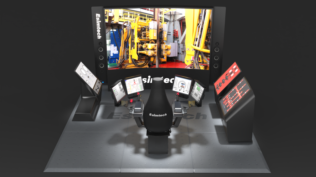
The hardware part of the drilling simulation training system is highly simulated on-site real equipment. Various panel layouts, operation methods, parameter display methods, etc., are consistent with the production site.

The system combines advanced computer industrial control technology, artificial intelligence technology, scientific visualization technology, virtual reality technology and advanced network technology, as well as strict simulation of the actual process of drilling engineering, and adopts high-reliability classic physical and mathematical models to provide users with the following Various training operations such as drilling, drilling, well control, equipment fault detection, and handling of drilling accidents and complicated situations.
The three-dimensional graphics synchronized with the operating conditions will be projected on the front screen to produce a visual effect similar to that of the scene, accompanied by realistic sound effects of the on-site equipment environment, giving people an immersive sense of immersion and realism.
The advanced software system can create corresponding snapshots based on real on-site well conditions and history information, so as to conduct highly simulated on-site training operations for trainees. The non-sequential driller operation mode breaks the fixed operation mode that the previous training exercises must be done step by step, so that the trainees can operate arbitrarily based on the snapshot. The drilling simulator realizes a high degree of simulation from well conditions to equipment operation, which greatly improves the operational flexibility of the trainees, and greatly improves the training efficiency and training effect of the trainees.
Programs Of Drilling Simulation Training
1. trip module
(1) Normal trip in operation
(2) Operation in case of resistance when trip in
(3) Normal trip out operation
(4) Operation in the event of stuck drilling
2. Drilling module
(1) Normal drilling and picking upstand (single)
(2) Normal drilling and drilling with bouncing bit
(3) Drilling in low-pressure formation
3. Downhole accident processing module
(1) Judging and treatment of wall sticking
(2) Judging and treatment of sand settling
(3) Judging and treatment of balling up
(4) Judging and treatment of hole collapse
(5) Judging and treatment of key seating
(6) Judging and treatment of hole shrinking
(7) Well immersion (gas immersion, brine immersion)
(8) Fishing tap
(9) Junk milling4. Shut-in operation
(1) Shutting in operation when overflow occurs while drilling
(2) Shutting in operation when overflow occurs while tripping in and out
(3) Stripping after shutting in when overflow occurs while tripping out
(4) Shutting in operation when overflow occurs while tripping in and out collar
(5) Shutting in operation when overflow occurs in barren hole
5. Cementing operation
(1) Running casing
(2) Drilling out plug
(3) Cementing
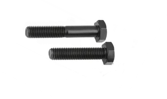
Bolts are cylindrical threaded fasteners. Usually, the bolt is composed of a thread area, a shaft area, and a head area. There is only a part of the threaded area, followed by the unthreaded area. A fully threaded bolt is a bolt without a shaft. Partially threaded bolts are ordinary bolts, and is not fully threaded, but only a part. So, Which is better between the two types of bolts.
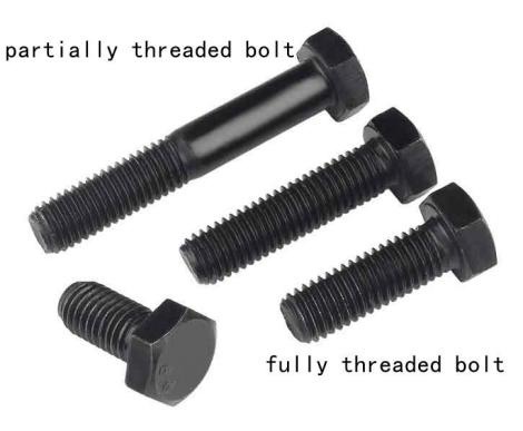
What are full-threaded bolts?
Fully threaded bolts are generally shorter in length. The thread length of such bolts is equal to the length of the bolt, with threads running through the entire length of the bolt from the head to the end.
What are partially threaded bolts?
Where longer bolts are required, the thread length does not need to be too long. Therefore, in the production of standard parts, only a part of the threads on the long bolts are processed to save processing costs. Partially threaded bolts have an unthreaded portion under the head, this unthreaded portion is called the grip length, and this is the partially threaded bolt. Due to the large force of many connectors, the half-threaded part is on the outside of the joint of the workpiece, while the inner part of the force is smooth without threads, which can improve the mechanical strength of the bolt and help to withstand greater torque.
Why Choose Full Thread Bolts?
If clamping strength is of greatest interest and alignment and shear strength are less of an interest, then fully threaded bolts may be an option. A fully threaded bolt means that all the tension applied to the bolt is distributed over the entire structure, which means it can handle more force than a partially threaded bolt. Full threaded bolts are used in environments that rarely require shear and tend not to loosen much. Once installed, a fully threaded bolt spreads pressure along its entire length, with the greatest holding pressure at the head where it meets the material being held.
Why Choose Partially Threaded Bolts?
The length of the non-threaded portion of a partially threaded bolt can vary depending on the specific application of the bolt. When using partially threaded bolts, the unthreaded portion can be brought into the threaded hole as part of the bolt-through application. Nuts and washers are threaded on the ends.
Partially threaded bolts are best used where alignment and shear resistance is important. The grip length of the bolt can provide the required alignment. When your project requires a lot of force to hold things in place, partially threaded bolts can provide the required resistance. The unthreaded portion is also referred to as the “grip length” and does not include weak points that can lead to shearing. This is because there are no threads in the grip length and no weak points that could lead to cracking or bending. So in order to shear such a bolt, a huge force is usually required.
How To Choose
When choosing a fully threaded bolt vs a partially threaded bolt, consider whether you need a maximum grip or maximum shear protection. If you need a grip, find the correct full-threaded bolt made of the material you need. If you are more concerned about shearing, choose a partially threaded bolt that will help prevent shearing.
Different partially threaded bolts have different grip lengths, so consider choosing a specific grip length before purchasing.
One of the easiest ways to get this information is to ask a fastener expert to help you. If you buy bolts from KENENG, it shouldn’t be very difficult because the people we hire are very knowledgeable about these things.
Subsea oil and onshore oil are essentially the same, both are liquid to semi-solid mixtures of hydrocarbons (organic substances, mainly alkanes, naphthenes, and aromatics). Oil on land can also be divided into marine crude oil and continental crude oil. Marine crude oil is formed from organic matter in ancient oceans, while continental crude oil is formed in lakes on ancient land.
Exploring and developing oil and gas in the ocean is the focus of modern marine geological exploration. It requires a large drill ship or platform to load drilling equipment to drill on the coast or offshore.
Drilling ships can be divided into single body and double body (suitable for water depth of 30-200 meters).
Platforms include bottom-mounted (suitable for water depths less than 30 meters) and pile-inserted (suitable for water depths of about 90 meters) fixed platforms, as well as semi-submersible floating platforms (suitable for water depths greater than 200 meters), which can be selected according to actual needs.What is the Difference Between Offshore Oil Drilling and Land Drilling?
1. The composition of organic matter and the ratio of some chemical elements in offshore oil are different from those in continental oil.
2. In terms of exploitation, the exploitation of land crude oil and seabed crude oil is different. Conventional crude oil on land is relatively easy to exploit, while the exploitation of seabed crude oil involves more complex processes, including platform construction, drilling, and pipeline laying, which are different from land oil exploitation.
One is how to erect the derrick stably above the water surface and withstand the attack of wind and waves.
The second is how to build a special wellhead device between the turntable and the seabed to isolate the seawater from the wellbore.
Third, there are fewer vertical wells and more inclined wells in offshore drilling, so there must be offshore drilling platforms that can ensure the normal operation of drilling rigs and other drilling equipment.
3. The cost of offshore drilling is high, about 3 to 10 times higher than that of land drilling.
Chengdu Esimtech Petroleum Equipment Simulation Technology Co., Ltd. is based on the Sichuan Provincial Department of Education Petroleum Engineering Computer Simulation Technology Key Laboratory. Esimtech is a company engaged in scientific research, design, production, maintenance, sales and computer application technology in the field of oil and gas industry An integrated high-tech enterprise.

Esimtech is committed to the development of simulation and simulation systems for petroleum engineering and petroleum equipment, and has achieved a series of application results with completely independent intellectual property rights, continuously providing users with the best products and creating value for users. After more than 20 years of persistence and unremitting efforts, it has successively developed petroleum engineering such as drilling, well control, logging, oil production, gas production, downhole operations, oil and gas gathering and transportation, fracturing and acidizing, drilling rig installation, coiled tubing, and snubbing operations. Training simulation system, the product line covers the complete field of oil and gas industry application sites. In addition, the drilling simulator is constantly updated and the technology is becoming more and more mature. It has become recognized by the industry as the drilling simulator product with the most complete functions, the best performance and the most reasonable price at home and abroad.