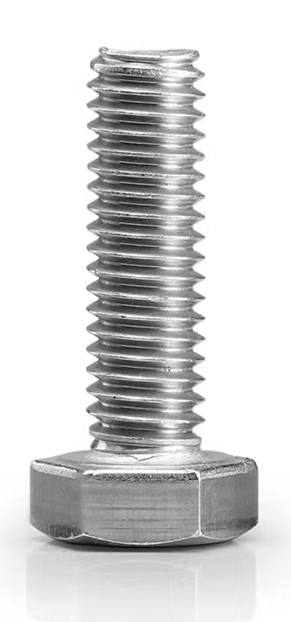
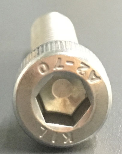
Socket screws with a cylindrical head, also known as socket head bolts, cup head screws, and socket head screws. Although they have distinct names, they both mean the same thing. There are also 4.8, 8.8, 10.9, and 12.9 hexagon socket head screws that are regularly used. It is sometimes referred to as a hexagon socket screw or hexagon socket bolt. It has a hexagonal and cylindrical head.
Classification of hexagon socket head cap screws
They are classed as carbon steel, stainless steel, and iron based on the materials.v Stainless steel SUS202 hexagon socket head cap screws are commonly used stainless steel materials. There are SUS304 hexagon socket head cap screws and SUS316 hexagon socket head cap screws made of stainless steel.
The iron substance is classified based on the hexagon socket head screw's strength grade. There are hexagon socket cap screws rated 4.8, 8.8, 10.9, and 12.9. High-strength and high-quality hexagon socket head cap screws are grade 8.8-12.9 hexagon socket head cap screws.
According to the head shape
The hexagon socket screws are classified based on the shape of the hexagon socket screws' heads. The cylindrical head hexagon socket screws are the most widely used.
The hexagon socket screw can also be separated into half round head hexagon socket bolts, also known as pan head hexagon socket bolts, and countersunk head hexagon socket bolts based on the shape of the head.
The countersunk hexagon socket bolt's head is flat, and the inside of the bolt is hexagonal as well. Headless hexagon socket bolts, also known as stop screws, machine screws, and set screws, are also widely used. There is also a flower-shaped hexagon socket screw that is difficult to find or acquire on the market.
The production standard of hexagon socket head screws
The production standard of hexagon socket head screws is determined by whether the standard is national, German, British, or American. Each standard is unique.
Take hexagon socket head screws, for example, which have national standards such as grade 8.8 hexagon socket head screws for half teeth GB 5782, grade 8.8 hexagon socket head screws for complete teeth GB 2783, and grade 8.8 hexagon socket head screws GB 70-85 DIN912.
All product sizes in production must meet applicable criteria, and the product quality of each screw must meet the ISO 9001-2000 quality standard system certification. As a result, the manufacturer must create sturdy and dependable items. Furthermore, the standard GB 70-85 DIN912 for grade 8.8 hexagon socket head screws requires that the tensile strength of the hexagon socket head screws produced by the manufacturer be greater than 640MPa, and the standard GB 2076 for grade 4.8 hexagon socket head screws requires that the tensile strength of the hexagon socket head screws produced by the manufacturer be greater than 320MPa, the thread gauge M4 diameter must be equal to or less than 7mm, and the minimum dia.
Common standards for Grade 12.9 hexagon socket head cap screws
Grade 12.9 hexagon socket screws are the most often used series of high-strength bolts: grade 12.9 hexagon socket screws are typically employed in situations requiring excellent mechanical performance. Injection moulding machinery, hydraulic equipment, mould assembly, and other places are examples. After heat treatment, the surface hardness of grade 12.9 hexagon socket screws can reach 39-44 degrees. All grade 12.9 hexagon socket screws are manufactured in accordance with the German standard DIN912, the national standard GB / t70.1, the American Standard, and the British standard. American grade 12.9 socket head screws are available in sizes ranging from # 4 to 1-1 / 2, while British grade 12.9 socket head screws are available in sizes ranging from 1 / 4 to 1-1 / 2.
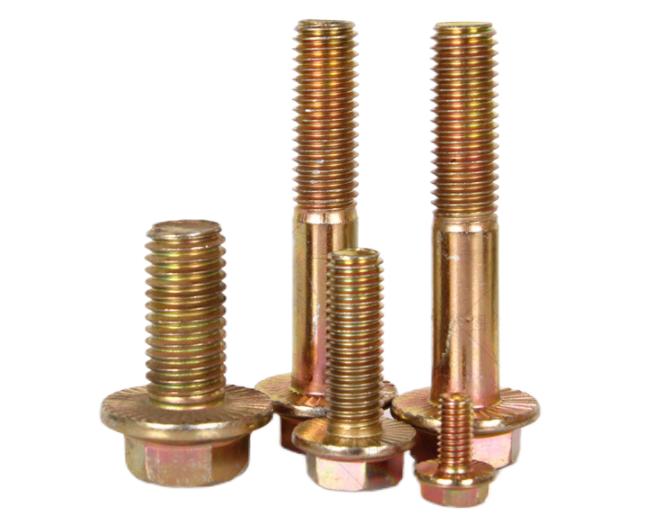
Grade 12.9 hexagon socket bolts are available with knurled or non-knurled heads. Grade 12.9 hexagon socket bolts typically have knurled heads, whereas low-strength hexagon socket bolts do not. Grade 4.8 hexagon socket bolts, for example, do not have knurled heads.
The surface of grade 12.9 hexagon socket bolts is cyanided and blackened. The product itself also has certain anti-rust properties. These 12.9-Grade high-strength bolt series goods, on the other hand, are generally utilised in exported equipment, and the surface of the 12.9-Grade hexagon socket head screws will be corroded by consumers in various hostile situations during transportation (such as shipping). However, some equipment (such as bread machinery and baking equipment) demands that the supporting hexagon socket screws be nickel and zinc plated to improve the corrosion resistance and look of grade 12.9 high-strength bolts.
Advantages of KENENG hexagon socket head cap screws
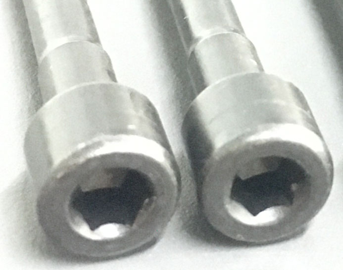
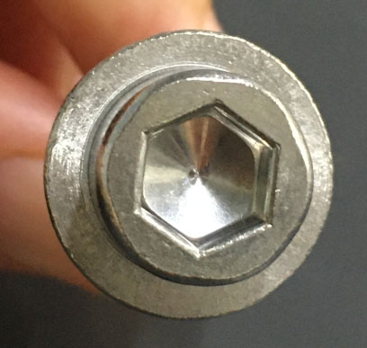
The regularity of the hexagonal inner wall's shape and polish.
The symmetry of hexagons
Inner hexagon socket bottom flatness
The above standards will be more stringent and accurate if the customer needs to make through holes for hexagon socket head screws.
KENENG has over ten years of fastener production experience, as well as specialised product designers and production lines. If you require regular products in large quantities or customised products based on your specifications, please do not hesitate to contact us.
The various oil drilling tools are all necessary for the extraction procedure. Some of the equipment, however, contributes more to the drilling operation. They help to reduce the cost, risk, and environmental impact of oil drilling.
Sand Pumps
Sand pumps, one of numerous pumps used in oilfield drilling, are utilised to move deposits away from the drilling site. Sand pumps are most commonly found in fluid tanks containing oil or other fluids and sand. These pumps rotate a grooved disc around a central axis.
Any particles that come into touch with the grooves on the surface will be removed and transported elsewhere via a pipe network. Despite its nickname, "sand pumps," these pumps also move other materials. Sand pumps, in addition to tank maintenance and cleaning, replace the use of other machinery or manual labour to move particles away from the area of the oilfield.
Shale Shaker
The most significant component of a rig's solids separation and control system is the shale shaker, which separates the mud from the cuttings. The mud is used to cool the drill bit once it has separated. If all goes as planned, the drillers will be able to use these fluids several times.
Separating mud disposal allows for lower drilling costs and environmental impact. The performance of the remaining downstream controlling devices is inextricably linked to good drilling fluid management.
Mud Cleaners
The mud collected from the cuttings is used to cool the drill bit. Mud cleaners function to keep the drilling fluids (mud) clean so that the drill runs smoothly. Because heavy muck stops the drill and increases downtime, it is critical that the mud be as clean as possible before it reaches the drill.
The mesh used in mud cleaners features microscopic pores that keep contaminants out of the mud.
Degassers
Once the fluids have been separated from the large particles, any trapped gas and air must be eliminated. Degassers are necessary to remove gases from the oilfield such as hydrogen sulphide, methane, carbon dioxide, and others. This improves safety by minimising the likelihood of gas explosions.
Stabbing Guides
Drilling pipes might become misaligned, resulting in damage and downtime. Stabbing guides are essential to ensure precise and damage-free connections. They also protect pipelines from damage and corrosion. In more demanding applications such as oil drilling, stabbing guides can also aid protect against severe temperatures, impacts, and corrosion.
Blowout Stoppers
Blowout preventers (BOPs) are critical during drilling to ensure the safety of the workers. Ram BOPs and Annular BOPs are two prominent examples of the numerous BOPs.
Blowout preventers are among the most important oil rig equipment for protecting people from dangerous blowouts and ensuring their safety.
These devices, along with a number of others, must be integrated into an oilfield drilling workflow. The oilfield equipment indicated above is required for a project to successfully drill for oil. Understanding how they interact with one another is much more important.

Esimtech can design and manufacture simulation training equipment for the oil and gas industry, such as drilling and well control simulators, downhole operation simulators, emergency drill training simulators, and so on. It can also be customised to your specifications; if you require this, please contact us.
Based on X-ray theory, the alloy analyzer was born. It is primarily utilised in the military, aerospace, steel, petrochemical, electric power, pharmaceutical, and other areas to determine elemental composition of metal products.

How does the Alloy Analyzer Work
The alloy analyzer is a type of XRF spectroscopic analytical tool that can be used to confirm and quantify certain elements in a product. It can identify the specific element based on the X-ray's emission wavelength () and energy (E), and it can quantify the amount of that element by measuring the density of the related ray. XRF can thus assess the elemental composition of substances.
Each atom contains a set number of electrons (negatively charged particles) that orbit the nucleus. And the amount of electrons in the nucleus equals the number of protons (positively charged particles). The number of protons can be calculated from the number of atoms in the periodic table. Each atomic number is assigned to a specific element name, for as iron, which has the element name Fe and the atomic number 26. Energy-dispersive X fluorescence and wavelength dispersive X fluorescence spectral analysis technology was developed and used to the three innermost electron orbitals, namely K, L, and M. The K orbital is the closest to the nucleus, and each electron orbital corresponds to a certain element with a specific energy layer.
Photons of high-energy primary rays generated by the X-ray emission tube strike the sample element during XRF analysis. These fundamental photons have enough energy to derail the innermost electrons, known as the K or L layers. At this point, the atom transforms into an unstable ion. Because electrons seek stability instinctively, electrons in the outer L or M layers will enter the space that makes up the inner layer. As these electrons move from the outer layer to the inner layer, they emit energy known as secondary X-ray photons.
The entire process is known as fluorescence radiation. Each element's secondary rays will have distinct properties. The energy differential between the inner and outer layers during the electron conversion process determines the quantity of energy created by X-ray photon fluorescence radiation. The K energy of an iron atom Fe, for example, is around 6.4 kiloelectron volts. The number or density of X-rays emitted by a certain element over a given time period can be used to calculate its amount. A typical XRF energy distribution spectrum depicts photon density distribution at various energies.
What should I pay attention to when using a Handheld Alloy Analyzer?
When determining the composition of materials with a portable X-ray fluorescence spectrometer (handheld alloy analyzer), three significant criteria must be considered.
Material Composition
From magnesium to heavier elements, the handheld spectrometer alloy analyzer can quantitatively analyse more than 90% of the elements in the periodic table. Most of the elements used in commercial alloys are represented by these quantifiable elements. According to the material composition information collected, the XRF analyzer can detect aluminium alloy, stainless steel, chromium-molybdenum alloy or base alloy, bronze alloy, various other copper alloys, solder, titanium alloy, tool steel, nickel, and cobalt. Elements Many so-called "superalloys" are brand-matchable. The handheld alloy analyzer, however, cannot identify elements lighter than magnesium. Alloying elements such as lithium, beryllium, and carbon are examples of undetectable elements.

The Surface Temperature of the Alloy Analyzer Sample
The physical properties of X-rays employed in XRF analysis technology do not change much when the temperature of the sample changes. Furthermore, the analysis device's design purpose is to be unaffected by changes in ambient circumstances and to always provide reliable measurement performance. Thermal drift and performance deterioration will not occur when the analyzer is operated in the temperature range of -10 °C to 50 °C.
When the sample temperature exceeds roughly 100 °C, the alloy analyzer is not altered, and the sample can be measured normally. However, if the temperature rises above this level, the polypropylene fibre film that forms part of the analyzer glass may be destroyed.
How do users of handheld alloy analyzers go about purchasing high-quality handheld alloy analyzers? This is a critical question. At the end of this post, I recommend Drawell, a maker of high-quality handheld alloy analyzers. Drawell Scientific is a reputable maker of portable alloy analyzers. Always give high-quality products to clients worldwide. They may deliver high-quality alloy analyzers such as the Handheld handheld XRF Gold Analyzer (TrueX Gold) and the Handheld Alloy Analyzer (TrueX 800).
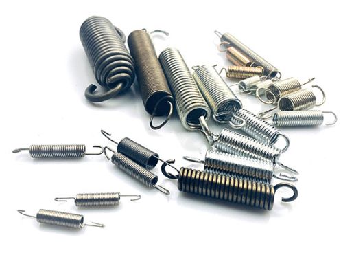
Spring can be found in a variety of machinery. From consumer goods to large industrial equipment, removing anything requiring mechanical components may reveal a spring, which is a mechanical storage device. Types, properties, and applications of spring are discussed in this article.
Cylindrical Helical Spring
Circular cross-section type
It's a circular-section compression spring.
The characteristic line is linear, stiff, has a simple structure, is easy to manufacture, and has a wide range of applications. It is mostly employed in mechanical equipment as a buffer, vibration reduction, energy storage, and control movement.
Rectangular cross-section type
The cylindrical spiral compression spring with a rectangular cross-section offers more stiffness and absorption energy than the circular section type under the same space conditions. The characteristic line approaches the straight line, and the stiffness approaches the constant.
Flat-shaped section type
The cylindrical helical spring with a flat-shaped section has more storage energy and compression than the circular cross-section kind. As a result, it is frequently employed in applications such as engine valve mechanisms, clutches, and automatic transmissions.
Variable pitch type
When the load is increased to a particular degree, the spring gradually tightens the spacing from the section, causing the stiffness to increase. As a result, its autobiography frequency becomes variable, which has a positive effect on removing or reducing resonance and is extensively utilised in high-speed load-changing mechanisms.
Multi-wire type
Steel wire rope is the material. The contact between the steel wires is somewhat slack when not loaded. When the external load hits a particular threshold, the contact becomes tight and the spring rigidity increases. It is commonly utilised in weaponry and aircraft engines.
Extension Spring
The performance and properties of the cylindrical helical spring with a circular cross-section are the same. It is mostly employed in tensile load settings.
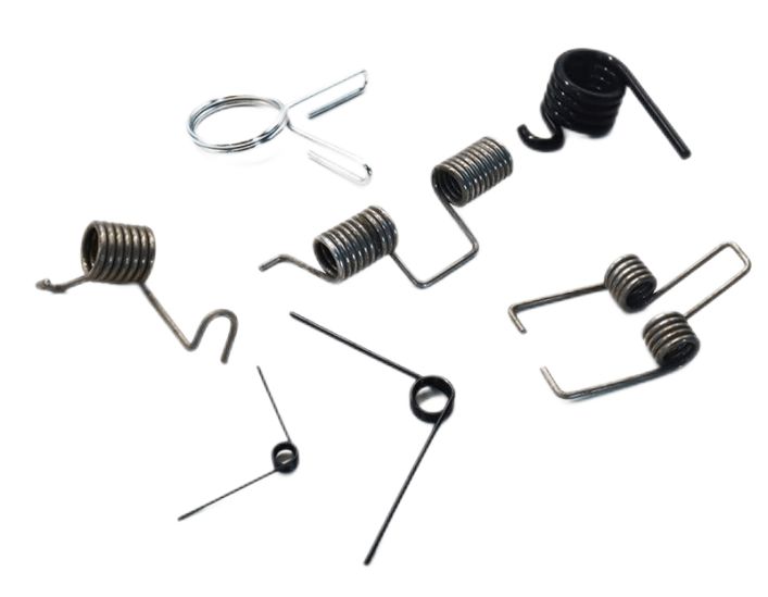
Torsion Spring
The torsion spring is under torsion load and is mostly utilised for compression, energy storage, and transmission system elasticity. It has a linear characteristic line and a wide range of applications, including measuring and metering as well as the compulsory air valve closure mechanism.
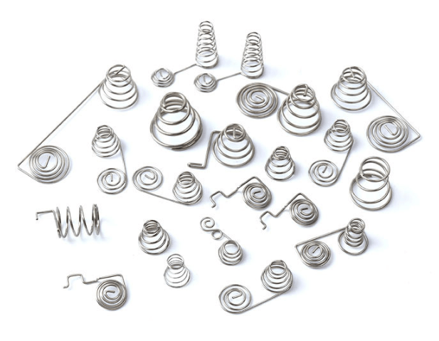
Spiral Spring
The spiral spring can absorb more energy in the same space than other springs, and the friction between the plates can be employed to dampen vibration. It is frequently employed to absorb thermal expansion deformation. The downside is that the distance between the boards is narrow and difficult to quench, making spray treatment impossible. Furthermore, the manufacturing accuracy is insufficient. It can be used as both a measuring and pressing element.
Torsion Bar Spring
The torsion bar spring has a simple structure, but the criteria for material quality and production precision are high. It is mostly utilised as a suspension spring in automobiles and compact vehicles.
Ring-shaped Spring
The ring spring is widely used in occasions that need to absorb large energy but is limited by space, such as springs for locomotive traction devices, and buffer springs for cranes and cannons.
Leaf Spring
A leaf spring is a metal piece that has a rectangular cross-section, which is mainly used for situations when the loading and deformation are not large. It can be used as a sensitive element in the detection instrument or automatic device.
Plate Spring
The plate spring is made of numerous spring steel plates bonded together. It is commonly employed as a suspension device in automobiles, tractors, and trains as a buffer and vibration reducer.
Rubber Spring
The distinguishing line progressively increases in length. This rubber-metal helical spring has greater stiffness than a rubber spring and greater damping than metal springs. As a result, it has great loading capacity, strong vibration reduction, and wear resistance, making it excellent for suspension structures for mining machinery and heavy vehicles.
Rubber-metal Spring
The distinguishing line progressively increases in length. This rubber-metal helical spring has greater stiffness than a rubber spring and greater damping than metal springs. As a result, it has great loading capacity, strong vibration reduction, and wear resistance, making it excellent for suspension structures for mining machinery and heavy vehicles.
Air Spring
An air spring is a non-metallic spring that achieves elastic properties by compressing air. It is commonly employed in vehicle suspension devices, which can significantly improve automotive power performance, therefore air springs are frequently utilised on vehicles and trains.
Geological exploration wells, pre-exploration wells, detailed exploration wells (evaluation wells), and development wells (including inspection data wells, production wells, water injection wells, adjustment wells, and so on) are the most common types of oil drilling. It can be separated into vertical wells, horizontal wells, and some other specific structure wells based on the well structure.
Production Well
Production wells, also known as development wells, are wells drilled during the oilfield development stage for oil and gas production, and include oil (gas) wells, water injection (gas) wells, adjustment wells, and so on. Drilling production wells rarely takes cores since the formation conditions are clear, the drilling speed is fast, and the cost is low.

(1) Oil (gas) wells: During the development of an oil field, wells drilled for the extraction of oil and natural gas are classified as oil-producing wells or gas-producing wells.
(2) Water (gas) injection wells: wells drilled to inject water and gas into the oil field to supplement and rationalise formation energy in order to increase recovery rate, and can be classified as positive injection wells (wells that inject water from the tubing to the formation) or reverse injection wells (wells that inject water from the casing into the formation).
(3) Adjustment wells: The supplemental drilling to improve the oilfield development effect refers to wells drilled in favourable positions during the oil and gas field development process to better develop the oil and gas fields based on the original well pattern.
Exploration well
Exploration wells, which include geological wells, pre-exploration wells, detailed exploration wells, and evaluation wells, are wells drilled for the goal of acquiring geological data. In most cases, exploration wells are drilled vertically.
(1) Pre-exploration wells: These are wells drilled to identify oil and gas reservoirs in favourable traps defined by intensive seismic examination and extensive geological research, as well as wells drilled to discover new oil and gas reservoirs in established oil fields.
(2) Detailed exploration wells: These are wells that are dug in identified oil and gas traps to prove the boundaries and reserves of oil and gas, as well as to comprehend the structure and oil production capability of oil and gas layers.
(3) Evaluation well: a well drilled to demonstrate the oil and gas area and geological reserves of the trap after the oil and gas reservoir is located in the preexploration well.
Drilling exploratory wells takes a long time and costs a lot because of the unknown formation conditions and the requirement to take cores and measure geological data.
Exploration wells include geological exploration wells, pre-exploration wells, and detailed exploration wells (evaluation wells). Oil production wells, gas production wells, water injection wells, and gas injection wells dug for oil production are one type of development well; the other is adjustment wells, supplemental wells, inspection of resource wells, and so on.
Directional well
In oil drilling, directional wells, which include horizontal and deviated wells, are wells drilled following the design trajectory for specific reasons and requirements, in addition to vertical wells. Since the 1990s, as drilling technology has advanced and improved, highly deviated wells, horizontal wells, and extended reach wells have been the development direction to satisfy the needs of oil and gas field exploitation.
(1) Horizontal well
A horizontal well is one that is drilled along the (nearly) horizontal direction to a fixed length and has a large well inclination of between 86° and 120°. Horizontal well technology has been developed since the 1990s because it can expand the exposed area of the produced oil layer, raise the oil output of the oil layer, and increase the recovery rate of the oil field. Horizontal wells have four curvature radius types: long, medium, medium-short, and short. Horizontal well drilling is a relatively challenging task that necessitates the use of specialised equipment, drilling tools, tools, instruments, and processes.
(2) Deviated well
Deviated wells refer to wells whose designed large inclination angle does not exceed 85°, and can be divided into low-inclination wells, medium-inclination wells, and high-inclination wells, among which medium-inclination wells are used more.
(3) Cluster wells
Due to the constraints of the ground, environment, and other conditions, as well as the requirements for rational use of land resources, it is often necessary to drill several or dozens of directional wells and one vertical well in a planned manner on a well site or platform during the development of an oil field. Cluster wells are the collective name for these wells. The average distance between cluster wells' wellheads (well spacing) is 23m. Cluster wells are frequently employed in offshore oilfield development because they lower the cost of building well sites or platforms and make oil well production management easier.
Deep and ultra-deep wells
It can be split into shallow wells (drilling depth less than 2000 metres) and deep wells (drilling depth greater than 2000 metres).
Wells with a drilling depth of 2000-4500 metres
Deep wells (drilling depths ranging from 4500 to 6000 metres)
Ultra-deep wells (wells drilled to depths greater than 6,000 metres)
Esimtech is a manufacturer of simulation training systems for the oil and gas industry, and its products include the whole oil and gas production line. Drilling simulators, well control simulators, emergency training simulators, and more are available. You can look at our product categories. If the product you require is not on the list, we can customise it to meet your specifications.