In laboratories, the centrifuge is a relatively frequent separating equipment. It is frequently employed in the separation of experimental materials in sectors such as biomedicine, petrochemistry, agriculture, food hygiene, and others. Since its inception, the lab centrifuge has undergone low-speed, adjusted-speed, and over-speed modifications. Its advancement is primarily represented in the two complementary elements of centrifugal equipment and centrifugal technology. In terms of rotation speed, desktop centrifuges fall into two categories: low-speed and high-speed centrifuges. The advent of general-purpose desktop centrifuges has blurred the distinctions between low-speed, high-speed, micro-volume, and large-capacity centrifuges. Numerous rotors offer scientific researchers a wide range of applications. The scope of application has become the top choice for scientific research institutes.
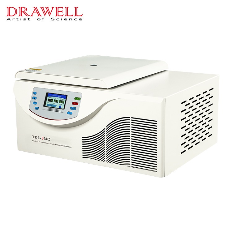
How to use a Benchtop Low-Speed Centrifuge
1.The benchtop low-speed centrifuge is set up on a level table or platform. The four rubber feet should be securely planted on a flat surface. Check for balance visually. Shake the centrifuge gently by hand to ensure that it is properly positioned.
2. Place the centrifuge tube into the rotor body after opening the door. The centrifuge tube must be in even-numbered symmetry (the centrifuge tube test solution must be weighed and added). Pay close care to tightening the screws on the rotor body, and double-check that the test tube is symmetrically placed and that the screws are tightened.
3. Close the door cover, make sure it's locked, and then check to make sure it's closed tightly.
4. Plug in the power adapter and turn on the power switch.
5. Configure the rotor number, speed, temperature, and time.
In the stopped state, the user can set the rotor number, speed, temperature, and time by pressing the SET button; in the running state, the user can only set the rotation speed, temperature, and time by pressing the set (SET) button; the centrifuge is in the setting state at this time, the running light is on, and the stoplight is flashing (in the stopped state, press the "SET" key to switch between timing modes). Cycle selection (in the running mode, press the "SET" key to cycle through time, temperature, and speed).
Set the rotor number as follows: When the decimal on the lower right corner of the rotor digital tube lights up, it will enter the rotor number setting, and then press the "" or "" key to select the centrifuge's rotor number this time. There are six different types of rotors to choose from. Note that the rotor number must be consistent with the rotor selected, and no errors can be set.
1.Set the speed: press the "SET" key until the decimal in the lower right corner of the last digital tube of the speed lights up, and then press the "" or "" key to determine the speed of the centrifuge at this time.
2.Set temperature: Press the "SET" key; when the decimal in the lower right corner of the final digital tube lights up, the temperature setting is entered; then press "" or "" to determine the centrifuge's operating temperature.
3.Set time: Press the "SET" key, and when the decimal in the bottom right corner of the final digital tube lights up, it will enter the time setting. Then, press the "" or "" key to ascertain the centrifuge's current working time (the longest time is 99 minutes), and the time counts down.
4.After completing the preceding four stages, hit the "ENTER" key again to confirm the rotor, speed, temperature, and time settings, and then press the "START" key to start the centrifuge.
5.When the rotor comes to a halt, open the door and remove the centrifuge tube.
6.Turning off the power switch turns off the centrifuge.
Precautions for the use of the centrifuge
The rotor cover can be put on the centrifuge platform or the experimental table while the Benchtop Refrigerated Centrifuge is pre-cooling. Make sure it's tight and floats on the rotor, because if it starts by accident, the rotor cover will fly out and cause an accident.
When the centrifuge produces a noise or vibrates, the power should be turned off immediately and the issue should be corrected as quickly as feasible. To prevent the machine from vibrating, the centrifuge tube must be symmetrically inserted in the shell. If only one sample tube is available, the other should be replaced with water of comparable quality.The centrifuge is simple to use and has no technical content, proper use and maintenance are still required. When an experiment fails, it causes a delay that is not worth the loss.
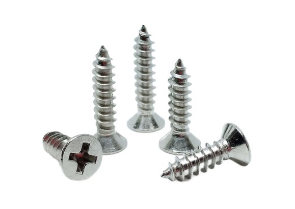
Self-tapping screws are commonly used to connect thin metal plates such as steel plates and saw blades. When connecting, first drill a threaded bottom hole in the linked piece, then screw the self-tapping screw into the threaded bottom hole.
The self-tapping screw on the consolidated material can drill one of the matched female threads in the pre-drilling of metal or non-metallic materials by its own thread. Its primary application is to join thin metal plates such as thin iron sheet, copper sheet, aluminium alloy, and other metals. The main distinction between self-tapping screws and conventional screws is that self-tapping screws have a pointed head and can pass through walls or other metal materials without drilling. It not only reduces the workload of fixed projects, but it also has user-friendly properties, thus it is extensively utilised in household appliances.
Structure of Self-tapping Screw
A self-tapping screw is made up of three parts: the head, the rod, and the rod end. Each tapping screw has four primary components: the head form, the screwing method, the thread type, and the end type.
Shapes of screw heads
Screw heads come in a variety of forms. There is a round head, a half round head, a flat round head, a round head flange, a flat round head flange, a pan head, a pan head flange, a countersunk head, a half countersunk head, a cylinder head, a spherical cylinder head, a horn head, a hexagon head, a hexagon flange head, and so on.
Screwing methods
The screwing method relates to how the screw head is twisted during installing and tightening the screw. External screwing and internal screwing are the two most common procedures. In general, the allowed torque of an exterior wrench is greater than that of any internal wrench.
External wrench
hexagon flange face, hexagon flange, hexagon torx, and so on
Internal wrench
Internal spline, internal hexagonal spline, internal triangle, internal hexagon, internal 12 corner, clutch slot, six-blade slot, high torque cross slot, and so on.
Types of screw threads
Screw threads come in a variety of shapes and sizes, including self-tapping thread, machine thread, plasterboard screw thread, fiberboard screw thread and other specialised threads. Screw threads are further classified as single lead, double lead, multiple lead, and high and low teeth double head threads.
Screw end forms
Ends are classified into two types: cone ends and flat ends. However, depending on the application, the screw-in end can process grooves, notches, or sections comparable to the shape of the drill bit.
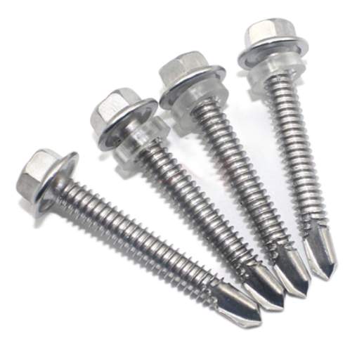
Features of Self-tapping Screw
1. A self-tapping screw is a screw that has a drill bit attached to it. A unique electric tool is used to make the hexagonal socket bolt. Drilling, tapping, fastening, and locking are all done at the same time. The self-tapping screw is mostly used for connecting and fixing some relatively thin parts, such as the connection of colour steel plate to colour steel plate, the connection of colour steel plate to purlin, the connection of wall beam, and so on. Its penetrating capacity is often no more than 6mm, with a maximum of 12mm.
2. Self-tapping screws are frequently exposed to the elements and have a high corrosion resistance. Its rubber sealing ring prevents water from entering the screw.
3. The self-tapping screw, also known as wood screws, is appropriate for usage with wood products. They are typically operated by hand. Due to labour constraints, these screws are often quite small, with a limited range of applications.
4. The self-tapping screw integrates the tap and the bolt. The tap is on the front, and the thread is on the back. Drill a hole in normally soft materials and then screw it in immediately. Tap out the thread before tightening the bolt thread. If the screw diameter is tiny enough and the material is soft enough, it can even be screwed into wood without prior drilling.
5. Self-tapping screws are typically defined by three parameters: screw diameter series, threads per inch length, and screw length. There are 10 and 12 screw diameter levels, with screw sizes of 4.87mm and 5.43mm, respectively. Threads per inch length is available in 14, 16, and 24 levels.
How Can Self-tapping Screws Be Easily Installed?
The main advantage of self-tapping screws is that they do not require nuts and can be locked and attached by their own thread. It is a pretty commonly used screw in everyday life. When self-tapping screws are inserted into holes in plastic metal materials, extrusion can generate internal threads in the holes, which is the primary function of self-tapping and self-drilling.
Self-tapping screws can be installed with an air screwdriver, a screwdriver, a pistol drill, or an electric hammer. In most cases, an electric hammer is required to drive concrete. Ordinary nails cannot be used to nail concrete walls with a mark over C10, however cement steel nails can be used directly if the bearing gravity requirements are not severe. If there is a high load bearing need, it must be secured using expansion screws, common plastic expansion pipes, and self-tapping screws.
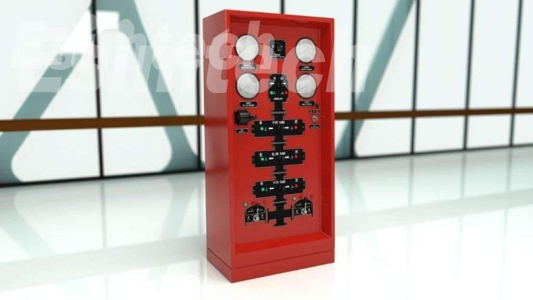
If a well leaks, an oil and gas business could face disaster. Fortunately, blowout preventers(BOPs) are effective tools for preventing this disaster. A blowout preventer (BOP) effectively closes the valve running underneath the machinery, preventing any liquid from surfacing in the case of a potentially catastrophic explosion or kick.
Blowout preventers (BOPs) simply keep the oil well's secure seal intact in order to avert damage and financial loss. Different BOP types perform somewhat different roles and may be more effective than others in resolving oil well troubles. To identify the type you need, you must first understand what each type accomplishes.
The types of BOP can be divided into ordinary BOP, universal BOP and rotary BOP.
In an emergency, the universal blowout preventer can be engaged to deal with any size drilling equipment and empty wells.
The rotating blowout preventer allows you to drill while spraying.
In deep well drilling, in addition to the two conventional blowout preventers, a universal blowout preventer and a rotating blowout preventer are frequently put on the wellhead, resulting in three or four combinations.
Rotary BOP
An annular blowout preventer is a massive, specialised BOP that is used to seal, manage, and monitor oil and gas wells.
The annular BOP is classified into two types based on the shape of the sealing rubber core: conical annular BOP and spherical annular BOP. Its structure is made up of four parts: the shell, the top cover, the rubber core, and the piston. When drilling tools, tubing, or casing are present in the well, the annular blowout preventer can use a rubber core to seal a variety of annular voids of varying diameters. It may entirely seal the wellhead while there is no drilling tool in the well, as well as the annular area formed by the kelly, coring tools, cables and steel wires, and the wellbore during drilling, coring, logging, and other operations. When the pressure lowering and regulating valve is used, the drilling tool can be forced into the drill pipe.
RAM BOPs
The shell, side door, oil cylinder, cylinder head, piston, piston rod, locking shaft, seals, ram, and other components make up the ram blowout preventer. Its functioning mechanism is to employ hydraulic pressure to push the piston, which drives the ram to close or open the wellhead, in order to achieve the aim of sealing and and opening the well.
A RAM BOP prevents oil from spilling out and foreign things from entering the well by closing it. It also allows for a controlled flow of oil as needed. Depending on your requirements, you may also find the following RAM BOP versions useful:
Line valves must be turned off.
Line choking valves.
RAMs with no vision.
Manifolds with chokes.
Pro tip: Some RAM BOPs have a remote control! Examine whether the needed model supports remote work.
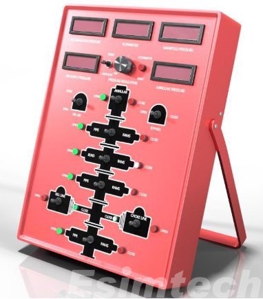
API Hardware
Flanged crosses, drilling spools, male and female adapters, and other critical BOP components are used to create and maintain high-quality BOPs. By customising the equipment, any BOP needs can be met. Whether you need to repair an old blowout preventer or design a new one for your oil well, quality API equipment can assist you.
Of course, Esimtech can manufacture oil and gas simulator equipment, including Blowout Preventers (BOPs) simulation training equipment.
A spectrophotometer is an important scientific device that divides complicated light into spectral lines. The spectrometer's measurement range normally comprises the visible light region with wavelengths ranging from 380 to 780 nm and the ultraviolet light region with wavelengths ranging from 200 to 380 nm. Because different light sources have varied emission spectra, different luminous bodies can be utilised as the instrument's light source. A tungsten lamp's emission spectrum: light of 380-780nm wavelength emitted by a tungsten lamp is refracted by a prism to produce a continuous chromatogram consisting of red, orange, yellow, green, blue, indigo, and violet; this chromatogram can be utilised as visible light. The spectrophotometer's light source. The spectral range of the spectrometer.

The visible light area of the spectrometer has a wavelength range of 400 to 760 nm, and the ultraviolet light region has a wavelength range of 200 to 400 nm. Because different light sources have varied emission spectra, different luminous bodies can be utilised as the instrument's light source.
The tungsten lamp emission spectrum: a prism is used to refract the light spectrum of 400760nm wavelength emitted by the tungsten lamp light source, resulting in a continuous chromatogram composed of red-orange, yellow-green, blue indigo, and purple; this chromatogram can be used as a visible light spectrophotometer light source.
The absorption spectrum of the substance
If a solution of a certain substance is placed between the light source and the prism, the spectrum displayed on the screen is no longer the spectrum of the light source, and several dark lines appear, indicating the light source emission spectrum of certain wavelengths. The solution absorbs and vanishes. This spectrum is known as the solution's absorption spectrum once it has been absorbed by the solution. various substances have various absorption spectra. As a result, the chemicals in the solution can be identified using the absorption spectrum.

Use of spectrometer
Nucleic acid quantification
The spectrophotometer's most commonly utilised function is nucleic acid quantification. The spectrometer can measure the concentration of oligonucleotides, single-stranded and double-stranded DNA, and RNA in buffer. The absorption wavelength of nucleic acid's maximum absorption peak is 260 nm. Because each nucleic acid's molecular makeup differs, so does its conversion factor. To quantify various forms of nucleic acids, the correct coefficients must be chosen ahead of time. 1OD absorbance, for example, is similar to 50g/ml dsDNA, 37g/ml ssDNA, 40g/ml RNA, and 30g/ml Olig.
After the test, the absorbance value is translated by the aforementioned coefficient to obtain the matching sample concentration. Select the correct programme before the test, enter the volume of the original solution and the diluent, and then test the blank solution and sample solution. However, the endeavour was not without its challenges. The most difficult problem for experimenters may be unstable readings. The larger the shift in absorbance, the greater the sensitivity of the device.
Direct quantification of protein (UV method)
This method involves directly testing the protein at 280nm. If you use the Warburg formula, the photometer will display the sample concentration immediately, or you can use the associated conversion technique to convert the absorbance value to the sample concentration. The protein determination procedure is straightforward: first test the blank solution, then test the protein directly. Because the buffer contains certain impurities, it is usually essential to remove the 320nm "background" information and turn this function on. The absorbance value of A280, like that of the test nucleic acid, must be larger than 0.1A, and the optimal linear range is between 1.0 and 1.5. The direct protein quantification approach is best suited for assessing purer, single-component proteins. The UV direct quantification approach is faster and easier to use than the colorimetric method; nevertheless, it is sensitive to interference from parallel compounds such as DNA; it also has low sensitivity and requires a higher concentration of protein.
Bacterial cell density
A laboratory spectrometer can be used to determine the growth density and period of bacteria. The OD600 method is the industry standard for monitoring the development of microorganisms in liquid cultures. As the blank solution, use the culture solution without bacteria, and then quantify the culture solution with bacteria after the culture. The OD value of the bacterial solution may appear negative at times during the experiment. The color-developing media is utilised, which means that once the bacteria have been grown for a while, they react with the medium and generate a colour change reaction. Furthermore, the analysed samples cannot be centrifuged, and the bacteria must be kept in suspension.
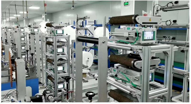
A web guiding system is a mechanism used in many industries, including printing, packaging, and textiles, to offer accurate alignment and control of a moving web or continuous material during industrial processes.
Various sensors and detectors are used by the web guiding system to precisely determine the location and alignment of the web material being processed. These sensors and detectors play an important role in providing feedback to the control system, which then modifies the guiding mechanism to keep the web in the proper position.
Ultrasonic sensors
Ultrasonic web guide sensors use high-frequency sound vibrations to determine the position and distance of objects. They can determine the position of the web edge by creating ultrasonic waves and monitoring how long it takes the waves to bounce back after impacting the web substance. Ultrasonic sensors are often used in edge guiding systems to enable precise and non-contact web edge detection.
Vision sensors
Using cameras and image processing algorithms, vision sensors photograph online content and analyse its placement and alignment. They can detect web elements such as edges, lines, and patterns and send real-time data to the control system for web directing changes. Vision sensors are incredibly versatile, and they can be used in edge, centre, and combination guiding systems.
Infrared sensors
Using infrared light, the infrared web guide sensor detects the presence and position of things. They can be employed in web guiding systems to identify the web edge by emitting infrared light and measuring the light's reflection or transmission when it comes into contact with web material. Infrared sensors are useful in applications where the web material is transparent or translucent, such as in the plastic film and glass industries.

Capacitive sensors
Capacitive sensors work by detecting changes in capacitance caused by the proximity of objects. They can determine the position of the web material by measuring capacitance changes when it comes into touch with the sensor. Capacitive sensors are commonly used in centre guiding systems to detect the position of the web material in relation to the centerline.
Laser sensors
Laser sensors use laser beams to measure distances and positions precisely. They can be employed in web guiding systems to precisely establish the position of the web edge by emitting laser beams and detecting the beams' reflection or scattering from the web substance. Laser sensors are suited for applications that require high precision and resolution.
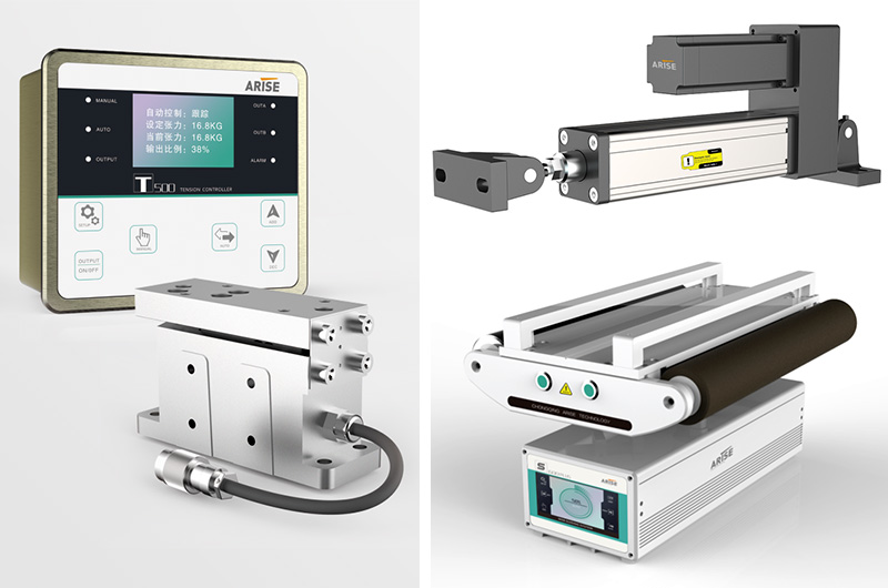
Load cells
Load cells are used to calculate the tension or stress on a web material. By placing them in the web route, they can supply input to the control system for tension control and web guiding modifications. To keep the web material tensioned and aligned, load cells are frequently used in web tension control devices such as brakes and clutches.
Types Of Web Guiding System
Edge Guiding
Edge guiding is the most common type of web guiding mechanism, in which the web edge guiding system modifies the location of the web material based on the detection of one or both web edges. Edge guiding systems detect the position of the web edge(s) and make adjustments to keep the web aligned along the desired path. Edge guiding systems can contain actuators such as steering rollers or guide rails to physically move the web material to the desired place.
Center Guiding
The technique of sensing the position of the web material's centerline and altering the guiding mechanism is known as centre guiding, also known as line guiding or line following. In centre guiding systems, sensors or detectors are often employed to measure the location of the web material in relation to the centerline and then make adjustments to keep the web aligned along the centerline. Centre guiding systems might contain actuators such as center-driven rollers or adjustable guide bars to centre the web material.
Role Of Actuators In The Web Guiding System
Web guide actuators are important components of a web guiding system because they physically change the position of the web material in response to data from sensors or detectors. Actuators are devices that convert electrical, hydraulic, or pneumatic signals from the control system into mechanical motion in order to move or control the position of the web material.

Steering Rollers
Steering rollers, also known as dancer rollers or idler rollers, are commonly used in edge guiding systems. They are supported by adjustable arms or brackets that can be moved horizontally or vertically to guide the web material. The position of the steering rollers is changed based on feedback from sensors or detectors to keep the web material in the appropriate area.
Guide Rails
Guide rails are solid structures or bars put parallel to the web route in edge guiding systems. They can be changed horizontally or vertically to direct the web information. The location of the guide rails is adjusted based on feedback from sensors or detectors to keep the web material aligned along the desired path.
Center-Driven Rollers
Center-driven rollers are used in centre guiding systems to direct the web material down the centerline. They are powered by a motor and can be adjusted horizontally based on sensor or detector feedback to centre the web material. The speed of the center-driven rollers is controlled by the control system in order to maintain proper web material alignment.
Adjustable Guide Bars
Adjustable guide bars are used in centre guiding systems to guide the web material along the centerline. They are stiff bars that can be adjusted horizontally or vertically based on sensor or detector data to centre the web material. Adjustable guide bars are typically installed on both sides of the web material and can be altered independently to maintain proper alignment.
Pneumatic or Hydraulic Actuators
Pneumatic or hydraulic actuators are utilised in web guiding system to provide accurate and strong control of the web material. Using pressurised air or hydraulic pressure, they generate mechanical motion and change the location of the web material. Pneumatic or hydraulic actuators can be used in conjunction with other types of actuators, such as steering rollers or guide rails, to achieve the desired guiding performance.