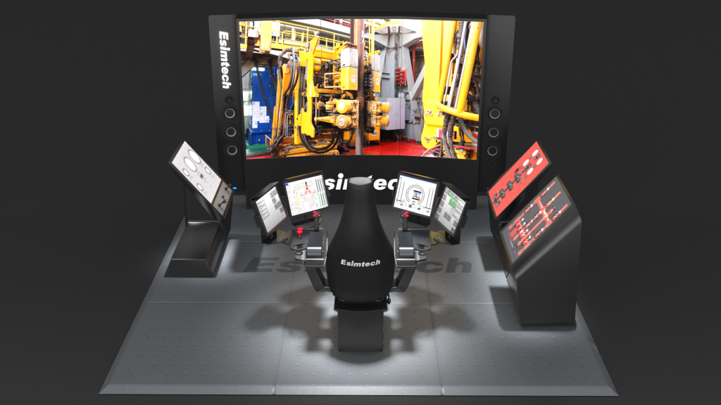
Drilling rigs are vital tools in the exploration, extraction, and construction industries. They are used to drill deep holes into the earth's surface, allowing important resources like as oil and gas, minerals, and water to be extracted. Drill rigs exist in a variety of shapes and sizes, each tailored to specific drilling needs. Understanding the various types of drill rigs and their capabilities is crucial when choosing the right equipment for a certain drilling operation. In this post, we will look at the various types of drill rigs and their functions, providing a full overview of the drilling technology globe.
Definition of a Drilling Rig
A drilling rig is a machine that drills holes or wells in the ground for a variety of reasons such as exploration and extraction of natural resources such as oil, gas, and minerals, as well as construction and geotechnical research. Drilling rigs are often mounted on trucks, trailers, or skids and contain a variety of drilling gear such as drill bits, drill pipes, and drilling mud systems. The rigs can be driven by electricity, diesel engines, or hydraulic systems and come in a variety of sizes and configurations to meet a variety of drilling needs.

What is the Function of the Drilling Rig?
A drilling rig is a mechanical apparatus that propels a drilling tool underground to collect physical geological data while exploring or exploiting mineral resources.
A drilling rig's principal job is to drill holes or wells in the ground for various purposes. The drilling rig's primary job is to drive the drilling tool into the hole and break the rock at the bottom, as well as to lower and raise the drilling tool. It can be used to assess the state of subterranean geology and mineral resources via drilling cores, ore cores, cuttings, gaseous samples, liquid samples, and so on. A drilling rig's exact function is determined by the type of drilling being performed, which can include
Exploration drilling: This technique is used to identify and assess subsurface resources such as oil, gas, and minerals.
Production drilling: A method of extracting oil, gas, and minerals from the earth's crust.
Geotechnical drilling is a technique used to collect soil and rock samples for engineering and construction reasons.
Environmental drilling is used to collect soil and groundwater samples and to monitor groundwater levels.
Water well drilling: The process of creating wells that supply drinking water to homes and businesses.
Construction drilling: Drilling used in construction to produce holes for building foundations, bridges, and other structures.
Drilling rigs play an important role in well completion and maintenance in addition to generating holes. They are used to install casing and tubing to prevent the wellbore from collapsing and being contaminated, as well as to execute well intervention activities such as well stimulation and remediation. Overall, drilling rigs are critical tools for accessing and utilizing the Earth's subterranean resources.
What Are the Different Types of Drilling Rigs Based on Classification Methods?
Drilling rigs exist in a variety of shapes, sizes, and configurations, each tailored to a specific drilling activity. Understanding the many types of drilling rigs is critical in picking the suitable equipment for a certain drilling project in the area of drilling technology. The following are the main types of drilling rigs, as classified by various methods:
Drilling equipment is typically classified as follows:
1. Standard land drilling rigs
2. The Desert Rig
3. Drilling rig mounted on a vehicle
4. Machine for coiled tubing
5. Well Drilling Rig Deviation
6. Offshore drilling rig
7. Drilling
1. In accordance with the drilling method
(1) Impact drilling rigs, including wire rope impact drilling rigs, vibration drilling rigs, and so on.
(2) Rotary drilling rigs, such as those used for rotary table drilling.
(3) Downhole power drilling tools, such as turbo drills, screw drills, electric drills, and so on.
2. Based on drilling and depth categorization
(1) Drilling rig for ultra-deep wells. A drilling rig with a drill pipe diameter of 114mm, a nominal drilling depth of over 7,000 meters, and a maximum hook load of over 4,500 kN is used.
(2) Drilling rig for deep wells. A drilling rig with 114 mm drill pipe diameter, a nominal drilling depth of 4000-7000 meters, and a hook load of 2250-4500 kN.
(3) Drilling rigs for medium and deep wells. A drilling rig with a drill pipe diameter of 114 mm, a nominal drilling depth of 1500-4000 meters, and a hook load of 900-2250 kN is used.
3. Depending on the power equipment
(1) The drilling rig is powered by a diesel engine. A drilling rig that is powered by a diesel engine via mechanical or hydraulic transmission.
(2) Drilling rig with AC drive. It can be used in oil fields with industrial power systems.
(3) Drilling rig with direct current drive. A DC motor powers the working unit.
4. Depending on the driving mode
(1) A single drive. The drawworks, drilling pump, and turntable are all powered by the same power unit. Most rigs employ this strategy. The unified drive can only accommodate one drilling pump; the other drilling pump must be operated separately. Although the unified drive drilling rig has a high power utilization rate and can be adjusted mutually when the engine fails, the transmission is difficult to install and modify, and its efficiency is low.
(2) Drive as a group. The power combination consists of independent drive and unified drive. This type of drilling rig has a higher power usage rate than a single drive.

What is the most common type of drill rig?
The most frequent form of drilling rig is determined by the specific application and geological conditions of the drilling operation. The rotary drilling rig, also known as a typical drilling rig, is one of the most regularly utilized types of drilling rigs.
Rotary drilling rigs are adaptable devices that can be used for oil and gas exploration and production, geothermal drilling, and water well drilling. They are usually placed on vehicles or trailers and run on diesel engines. While rotary drilling rigs are the most common, other types of drilling rigs, such as cable tool drilling rigs, top drive drilling rigs, and directional drilling rigs, are also used depending on the specific drilling project's requirements. Each type of drilling rig has advantages and disadvantages, and the rig used will be determined by the geological conditions, drilling objectives, and project budget restraints.
Esimtech is a high-tech enterprise in the oil and gas industry that combines scientific research, design, production, maintenance, sales, and computer application technology. Committed to the development of simulation systems for petroleum engineering and petroleum equipment, a number of application results with completely independent intellectual property rights have been obtained, as well as a number of domestic and international patents, and it has become a member of IADC and IWCF.
Through perseverance and unwavering efforts, it has developed petroleum engineering over the course of more than 20 years, including drilling, well control, logging, oil and gas production, downhole operations, oil and gas gathering and transportation, fracturing and acidizing, drilling rig installation, coiled tubing, and snubbing operations. Our product line covers the entire spectrum of oil and gas application sites.
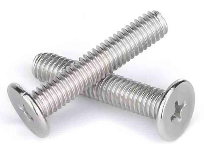
Stainless steel bolts can provide enough corrosion resistance in various industries. In addition to mechanical failure, stainless steel corrosion is mostly displayed as localized corrosion, which includes stress corrosion cracking, pitting corrosion, and corrosion fatigue. So, what are the advantages and disadvantages of stainless steel bolts?

Advantages of Stainless Steel Bolts
SUS310S, 309S, 316L, 316, 316Si, 317, 304, 304L, 309, 305, 31403, 321, 301, 202, 201, and other stainless steel product grades are available.
1. Adaptability is more powerful. If the metric thread size requirements are met, stainless steel bolts can be utilized. As a result, stainless steel bolts are more common than ordinary anchor bolts.
The distinction and relationship between anchor bolts and bolts
An anchor bolt is a type of bolt connection, and there are many other types of bolt connections.
The anchor bolt connects the screw section and the concrete base material in some way that cannot be detached, and only the nut can be disassembled. In the case of bolts, the nut can be unscrewed from the bolt and the two components separated, resulting in a detachable connection.
The anchor bolt is a post-anchoring technology that must be drilled first and then tightened into the screw to anchor. The bolts have already been drilled.
The anchor bolt's head is buried in the concrete substrate, while the bolt's head is exposed.
2. The installation is less complicated. The placement of prior typical anchor bolts was more difficult. However, the installation of today's stainless steel bolts is relatively simple, which increases user convenience.
3. There were fewer issues experienced during installation. There is no need to be concerned about standard anchor bolts tilting while drilling. Because of the analysis of the corrosion resistance and fracture causes of stainless steel bolts, while installing stainless steel bolts, you can directly drill holes and then install them, resulting in a virtually 100% success rate.
4. Doesn't cause any problems when not in use. It can provide safety, is reasonably easy, and does not damage the aesthetic as long as the hole is closed with stainless steel bolts or the additional section is eliminated.
5. Stainless steel bolts perform better during installation, resulting in greater bolt use.
6. Excellent corrosion fatigue and wear resistance. Under certain corrosive medium conditions, it is used in pumps, valves, and other equipment.
It can be recycled and reused completely during the recycling process. It is very much in keeping with the green environmental preservation aspect of modern workmanship.
Excellent tolerance to extreme temperatures. The hardness of the stainless steel bolt is sufficient, and the fastener after manufacture and processing has a good anti-oxidation capacity, and it can perform normally under high temperatures, so high temperatures will not cause too much disruption.
The force capacity is sufficient to suit daily requirements. The maximum load that stainless steel fasteners can withstand is moderate. Even though it is not as strong as high-strength bolts, the force capacity of stainless steel fasteners is sufficient for most people's daily needs.
Disadvantages of Stainless Steel Bolts
1. The initial investment is substantial. The life cycle cost, on the other hand, is rather cheap.
2. Incompatible with long-term storage or use. The production cost is significant, and it is prone to sticking if not dismantled for an extended period of time after locking.
3. When the force is too great, it is easy for the teeth to slip or break. The toughness is lower than that of common iron screws.
4.Stainless steel screws have a low strength. High-strength screws are often constructed of carbon steel or iron.
A spectrophotometer is an equipment that employs purer monochromatic light as incident light to measure the absorption of light by compounds and perform qualitative or quantitative analysis of substances. Digital spectrophotometers, UV spectrophotometers, fluorescence spectrophotometers, and other types of spectrophotometers are commonly used. During use, spectrophotometer measurement errors are common. How do these mistakes happen?

1.Polychromatic Light's Deviation from the Contrast Ear Law
Beer's law cannot be established unless the light emitted by humans is monochromatic. Even a spectrophotometer with a dual monochromator, however, can only produce nearly monochromatic light and cannot produce pure monochromatic light. It still has a narrow light passband and polychromatic light characteristics. Beer's law will deviate in either a positive or negative direction due to the polychromatic light. An ultraviolet spectrophotometer's spectral bandwidth is normally 1nm or 2nm, with a minimum adjustable slit of 0.1nm; a visible spectrophotometer's bandwidth is 6nm, or even more than ten nanometers.
The spectral bandwidth should be kept to a minimum. However, as the spectral resolution increases, the instrument's sensitivity decreases. As a result, when picking an instrument, the impact of various conditions should be examined. For example, when the concentration of the solution is low, the light is monochromatic, and the color of the light is purer, Beer's law can be roughly applied.
2.The effect of stray light
Stray light is defined as other wavelength components that enter the detector outside of the spectral bandwidth of the wavelength to be measured, and it is the primary source of error in spectrum measurement.
The reasons are the spectrophotometer's dispersion element, the mirror, the lens, and dust on the inner wall of the monochromator. Stray light has a greater influence at the edge wavelength of the spectrophotometer's working band due to the poor transmittance of the monochromator, the radiation intensity of the light source, and the sensitivity of the detector.
Stray light limit instrument analysis's upper limit can result in substantial measurement mistakes. In actual work, the absorbance of the sample is often measured at or near the absorption peak in quantitative analysis. If stray light is present at the analysis wavelength, the sample's transmittance rate is low, and most of the stray light is transmitted, causing the recorded absorbance to be lower than the true absorbance.

3.The impact of instrument noise on measurement Tool
Instrument noise is a good sign of instrument error. It represents the instrument's ability to prepare dilute solutions. It is an undesirable signal superimposed on the to-be-measured analytical signal. Scan the 100%T and 0%T lines to get the spectrophotometer's absolute noise level. The smaller measurement signal will be obscured if the instrument is noisy. In general, twice the noise is employed to describe the instrument's sensitivity.
4.Wavelength and absorbance precision
Each measured sample value should be measured at a given wavelength. The measured value will be erroneous if the wavelength error is significant.
Selection of measurement conditions
1. Selection of reference solution and solvent
To determine the absorbance of the sample, the spectrophotometer utilizes the light intensity of the reference cell as the light intensity of the person. Adjust the instrument so that the absorbance of the solution passing through the reference cell is zero, and then pass the same light through the sample. Because the absorbance truly reflects the concentration of the substance to be tested, the reference solution is critical.
Pure solvent or distilled water can be used as the reference solution if just the reaction product of the chemical is examined and the developer is absorbed. Use the developer solution as the reference solution if the developer has color and absorbs at the measurement wavelength. The developer and other reagents should be introduced in the same proportion as the sample.
Use the sample solution without the developer as the reference solution if the color of other components in the sample interferes with the measurement and the developer used has no color.
The correct solvent selection plays a vital role in improving the accuracy of the analysis. A high-purity solvent should be used to decrease the influence of impurities in the solvent; the solvent should not chemically react with the test material; the test substance must have a certain solubility in the solvent; and if the solvent itself does not absorb light within the measured wavelength range, When measuring absorption, the shortest available wavelength of common solvents should be used; if a volatile solvent is used, the absorption cell should be covered during the measurement.

2. Selection of test wavelength
When measuring the solution with a spectrophotometer, you must first select the appropriate measurement wavelength. The absorption curve of the tested solution is used to make the decision. In general, we select the greatest absorption wavelength as the measurement wavelength to improve sensitivity.
In some cases, the maximum absorption peak is very sharp, the absorption is too large, or there is interference nearby, and the other wavelengths in the absorption curve must be chosen for determination while ensuring a certain sensitivity (the curve is more Corresponding wavelength on the flat surface) to eliminate interference. Drawing the absorption curve is an effective tool and strategy for selecting the correct wavelength.In general, there are two causes of spectrophotometer error: the error generated by the instrument's quality and manufacturing process, and the error induced by variable measurement conditions. Because there are so many different types of spectrophotometers on the market, the most important thing is to find one that is right for you.
I strongly recommend Drawer Scientific's spectrophotometers towards the end of the article. Digital spectrophotometers, UV spectrophotometers, fluorescence spectrophotometers, and other spectrophotometers are available from them. You can get things that are appropriate for your needs. If you have any questions regarding selecting a spectrophotometer, you may consult the engineers, who will be pleased to assist you.
Mooring chocks are required for the secure and successful mooring of vessels, preventing the vessel from drifting, shifting, or causing damage to the vessel and its surroundings.
Marine mooring chocks of various varieties are used to keep vessels in place during various nautical operations.
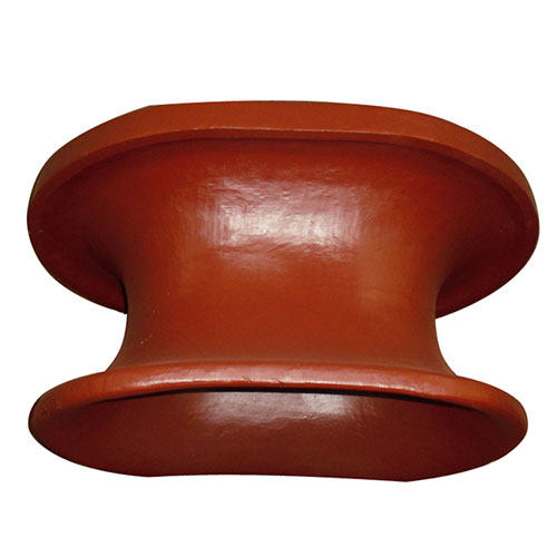
Roller Chock
The rollers on this mooring chock allow for smooth movement of mooring lines, reducing friction and line damage. Roller chocks are commonly used on ships with longer mooring lines, and they provide flexibility in mooring configurations.
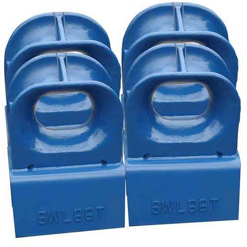
Closed Chock
Closed chocks have a closed circular or oval shape with a small aperture that allows mooring lines to go in a safe and constrained path. They prevent mooring line release by accident and are suitable for yachts with smaller mooring lines and limited space.
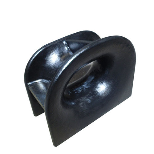
Open Chock
Open chocks have an open U-shape or V-shape with larger openings, making mooring line installation and removal easier. They provide for greater mooring arrangement and line angle flexibility and are often used in vessels with larger mooring lines and a broad deck area.
Bitt Chock
Bitt chocks are a cross between roller chocks and closed/open chocks. They have a roller on top and a closed or open shape below, allowing for smooth movement and secure mooring line closure. Bitt chocks are widely used in ports and harbours to secure the mooring of vessels with different mooring line sizes and deck area constraints.
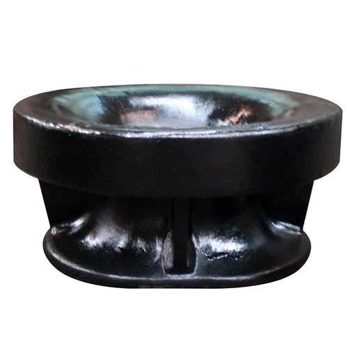
Panama Chock
Panama chocks have a curved form with a larger aperture that allows mooring lines to run in a wide, smooth path. They are frequently used in offshore and heavy-duty mooring operations and are suitable for vessels with longer mooring lines and bigger loads.
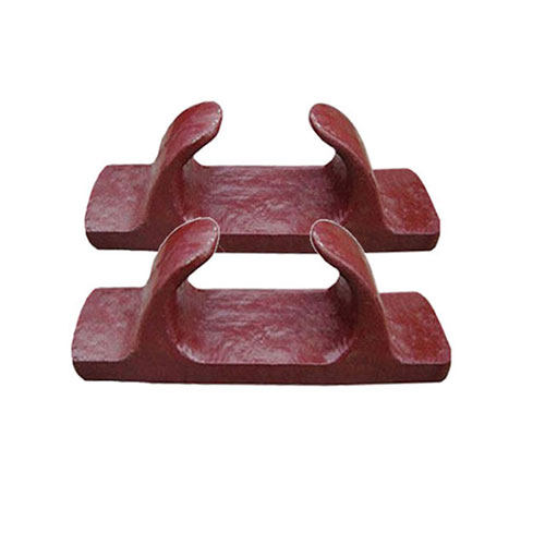
T-Head Chock
T-head chocks are T-shaped with openings on the top and sides for mooring lines to pass through. They are widely used in shipyards, dry docks, and marine construction projects and are suitable for vessels with complex mooring systems.
Chock with Hinged Chock
Hinged Chock
Hinged chocks have a hinged mechanism that allows the chock to move and hence accommodate varied mooring angles. They are suitable for vessels with changing mooring conditions and are frequently used in floating docks, offshore facilities, and other dynamic mooring situations.
Marine Mooring Chock Design and Construction
The design and construction of marine mooring chocks are critical to guaranteeing their efficiency and longevity in securing vessels during mooring operations.
Material choice
1. Choosing marine-appropriate materials (e.g., stainless steel, cast steel, ductile iron)
2. Ensuring materials are corrosion, wear, and fatigue resistant.
3. Compliance with applicable industry standards and regulations for marine-related materials.
Considerations for Design
1. Selecting the most appropriate type of mooring chock for the vessel and application.
2. Considering vessel size, type, and mooring line properties (e.g., diameter, breaking strength).
3. Calculate loads and forces on the mooring chock during mooring operations. (For example, static and dynamic loads).
4 Incorporating safety measures to maintain structural integrity and prevent overloading.
5. Considering environmental factors (such as wave loads and tidal currents), as well as site-specific concerns.
6. Include relevant elements such as rollers, hinges, and openings according on the design requirements.
Fabrication and construction
1. Making use of tried-and-true fabrication and production procedures for marine mooring chocks.
2. Using proper welding and fabrication techniques to achieve the desired structural integrity.
3. Throughout the fabrication process, thorough inspections and quality control are performed.
4. Coating the mooring chocks to protect them from corrosion and wear.
5. Carrying out load testing and certification to ensure the performance of the mooring chocks.
Advantages of Marine Mooring Chock
Mooring chocks are required for safe and efficient vessel mooring operations.
1. Mooring line securing
Marine mooring chocks are used to hold mooring lines, ropes, or wires from vessels to permanent or floating structures such piers, jetties, docks, buoys, and mooring bollards.
2. Distribution of load
Mooring chocks distribute the weights generated by vessels during mooring operations, reducing stress and strain on mooring lines and preventing vessel and mooring structure damage.
3. Aiding in friction and stability
Mooring chocks provide friction to prevent mooring lines from slipping or sliding, hence increasing vessel stability and reducing inadvertent vessel movements.
4. Increasing safety
Properly built and fitted marine mooring chocks help to the safety of mooring operations by preventing accidents, injuries, and damages caused by uncontrolled vessel movements. They ensure that mooring lines are securely held in place, lowering the possibility of line failure or disconnection when the vessel is moored.
5. Improving the efficiency of anchoring processes
Marine mooring chocks enable for smooth and controlled mooring operations, allowing vessels to be held in place safely and efficiently under a variety of environmental and operating situations.
6. Increasing operational efficiency
Marine mooring chocks increase the efficiency of mooring operations by allowing vessels to be quickly and securely moored in place. This lowers downtime, delays in departure and arrival, and improves the overall operational efficiency of marine vessels.
7.Safeguarding the vessel and the mooring structure
Mooring chocks distribute weights and protect mooring lines from overstress, protecting both the vessel and the mooring structure from potential damage caused by high winds. This extends the life of both the vessel and the mooring structure, reducing repair and replacement costs.
8. Providing adaptability
Mooring chocks are available in a number of shapes, sizes, and combinations, making them versatile and adaptable to a wide range of boats, mooring configurations, and environmental conditions. This increases mooring adaptability, allowing for a greater range of vessel sizes, types, and mooring requirements.
9. Improving the efficiency of anchoring processes
Marine mooring chocks enable for smooth and controlled mooring operations, allowing vessels to be held in place safely and efficiently under a variety of environmental and operating situations.
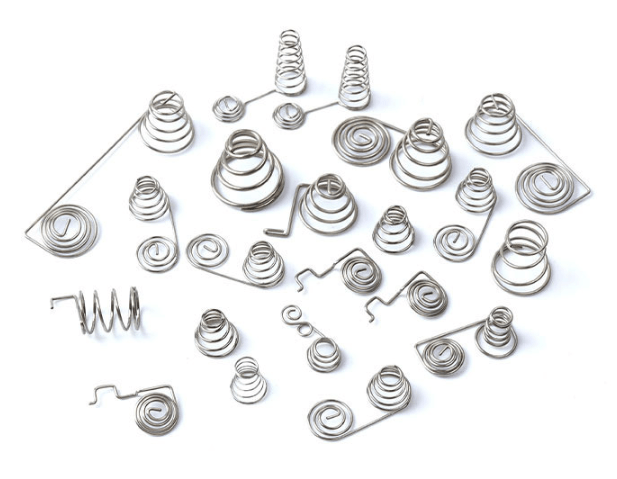
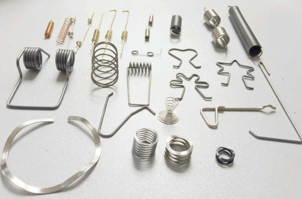
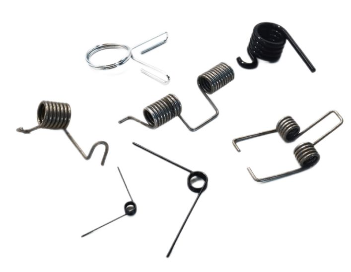
Compression springs, extension springs, torsion springs, volute springs, circlips, and other spring types are among the most prevalent. So, do you understand what the most common spring materials are and what are spring production process?
Metal spring materials that are commonly utilized
1. Spring steel, carbon spring steel: common grades include 70, 65Mn, T8, T9, and so on.
2. Alloy spring steel in grades such as 50CrV, 55CrSi, 60Si2Mn, and so on.
3. Stainless steel for springs, often used grades include 304, 316, 301, 201, 17-7PH, 12Cr18Ni9, 06Cr19Ni9, 07Cr17Ni7Al, and so on.
4. Copper alloys: Tin bronze, Silicon bronze, Beryllium-bronze, Brass/copper.
5. Nickel alloys: pure nickel, nickel-copper alloy, nickel-cobalt alloy, nickel-chromium alloy.
Non-metallic spring materials that are commonly utilized
1. Fluid material: gas (for example, a gas spring or a nitrogen spring), liquid (oil), or a gas-liquid mixture.
2. Ceramic materials are examples of inorganic materials. Rubber (rubber springs) and plastic fiber reinforced materials are examples of polymer materials.
Other special alloys include high-temperature alloy steel, Inconel, Hastelloy, high-speed tool steel, elastic element alloys, memory alloys, and so on.
What Kinds of Spring Coating Elements Exist?
Galvanized
Zinc is relatively stable in dry air, changes little, and is difficult to change color. In humid air, a white layer of zinc oxide or zinc carbonate forms. This dense film protects against additional rusting. Blue and white zinc, yellow zinc, colored zinc, and black zinc are common platings.
Plating with cadmium
Cadmium plating is commonly used to protect springs against corrosion, whereas cadmium plating is utilized to protect the inner metal. Because cadmium is an anode in comparison to iron, when it is pulled or cracked, the exposed iron metal beneath it can be protected by the cadmium plate's consumption. Cadmium is commonly found in atmospheric corrosion.
Copper plating
It is used in casting, nickel plating, chrome plating, silver plating, and gold plating.
Chrome plating
It is a silver-white metal with a microstrip blue finish. The chromium plating layer is extremely hard, with a hardness range of 400-1200HV depending on the plating solution composition and process parameters. The thermal characteristics of the chrome plating layer are excellent. Its gloss and hardness do not alter when heated below 500 °C. When the temperature exceeds 500 °C, it begins to oxidize and discolor. The hardness begins to decline at 700°C. The chromium plating layer has a low friction coefficient, particularly the dry friction coefficient, which is among the lowest of any metals. As a result, the chromium layer is abrasive.
Nickel plating
Nickel plating has a silvery white and yellowish look. Nickel plating is the electrolytic or chemical method of plating nickel on metals or nonmetals. Nickel plating is attractive and can be used to decorate. The cost is significant, and the procedure is quite difficult.
Tin plating
Tin plating has a silvery white look. It is a surface treatment process that uses tin plating on the surface of a metal, alloy, or other substance to add beauty and prevent rust.
Silver plating
The primary function of silver plating is to prevent corrosion while also increasing conductivity, reflectiveness, and attractiveness.
Galvanized titanium alloy
Galvanized titanium alloy is less expensive. It is corrosion resistant and stable, not easily rusted, and has a reasonably high hardness. It will be stronger than regular titanium alloys.
Spring zinc plating and cadmium plating play important roles
1. In humid air, a white layer of zinc oxide or zinc carbonate will form. This dense film protects against additional rusting. As a result, under typical atmospheric circumstances, the galvanized layer is used as a corrosion protection layer for springs. Springs in contact with solutions such as sulfuric acid, hydrochloric acid, and caustic soda, as well as springs working in humid air in an environment such as sulfur trioxide, should not be zinc-coated.
2. After plating, the galvanized layer is usually passivated. Passivation can improve the coating's protective function while also improving the surface's look.
3.The amount of protection is determined by the thickness of the zinc and cadmium coating. The thickness should normally be chosen based on the working environment during usage, and the thickness of the galvanized layer should be chosen between 6 and 24/m. The thickness of the cadmium plating layer should be chosen between 6 and 12/m.
KENENG has a big supply of different types of springs, such as compression springs, extension springs, torsion springs, die springs, battery springs, volute springs, disc springs, wire springs, flat spiral springs, etc, as well as bespoke springs, which can be designed and manufactured by our skilled spring design engineers based on your specific requirements or drawings.