Gas chromatograph and mass spectrometry is commonly utilized in the separation and identification of complex components due to its high resolution and sensitivity. The chromatographic, gas interface, mass spectrometer part (ion source, mass analyzer, detector), and data processing system are the key components of GCMS.
Gas-mass spectrometry (GCMS) is commonly employed in the separation and identification of complex components because of its high resolution and sensitivity. Without the need for sample preparation, GCMS can instantly determine the molecular weight of synthesized molecules.

Composition and fundamental concepts of gas-mass spectrometry (GC/MS)
In mass spectrometry, molecules of matter create charged particles by physical or chemical interactions in a high vacuum, and some of the charged particles can be further broken up. The mass-to-charge ratio (m/z, formerly m/e) of each ion is referred to as the mass-to-charge ratio (m/z). After the ions with different mass-to-charge ratios are separated one by one by the mass separator, the detector measures the mass-to-charge ratio and relative intensity of each ion, and the resulting spectrum is known as a mass spectrum.
Mass spectrometry is an analytical method that ionizes analytes, then separates them based on the ions' mass-to-charge ratio, and achieves the goal of analysis by measuring the peak intensity of the ions. Under certain conditions, macromolecular organic matter follows a certain pyrolysis law, which means that a specific sample can produce specific pyrolysis products and product distribution, and high-performance gas chromatography is used to analyze and identify the pyrolysis products. Original sample, according to this categorization.
The polymer sample is placed in a cracker and rapidly pyrolyzed at high temperature under highly controlled operating conditions to yield volatile tiny molecular products, which are then delivered to a gas chromatograph for separation and analysis. Because the composition and relative amount of broken fragments are directly related to the structure of the polymer to be examined, each polymer's cracking chromatogram has its own features; thus, the cracking chromatogram is also known as the thermal cracking fingerprint chromatogram.
Advantages of GCMS
The high separation efficiency of GCMS
Most pyrolysis gas chromatographs employ capillary chromatographic columns, which are capable of effectively separating complicated pyrolysis products, particularly tiny changes in macromolecular organic molecules and trace components in polymer materials. Reflect fragmentation chromatograms sensitively to locate related features.
High sensitivity
A hydrogen flame ionization detector with high sensitivity is commonly used in pyrolysis gas chromatography (GCMS).
Small sample size
The sample size is typically in the range of micrograms to milligrams, which is extremely useful for detecting just trace materials.
Rapid analysis time
The typical analysis time is 30 minutes.
When the cleavage product is complex, one analysis can take 1 to 2 hours.
A considerable number of information can be obtained
From qualitative and quantitative analysis, as well as the relationship between cracking circumstances and cracking products, the association between sample structure and cracking products, cracking mechanism, and reaction kinetics.
Numerous applications
GCMS can be used on any type of sample that does not require pretreatment. Viscous liquids, powders, fibers, elastomers, and other materials, as well as cured resins, coatings, and vulcanizates, can be directly injected for analysis.
Easy to promote
The pyrolysis injector has a basic structure and can be used for separation and analysis in conjunction with a gas chromatograph.
Can be linked to a variety of spectroscopic instruments
Any spectroscopic equipment that can be linked to a gas chromatograph can also be linked to pyrolysis gas chromatography.

Application of GCMS
It is appropriate for the separation and analysis of chemicals with a high molecular weight, a complicated structure, as well as challenging volatile and insoluble substances. The flash evaporation technique in pharmaceutical analysis can be used to assess the volatile components in Chinese herbal remedies.
The term "flash evaporation" refers to the fast heating of a sample at a lower temperature (lower than the sample's pyrolysis temperature) before cracking it to evaporate the volatile components in order to get a chromatogram. After that, the sample is broken at high temperatures to produce a cracked chromatogram. Important information about volatile components in the sample can be gained in this manner, which is highly useful in qualitative identification of the sample. Polymer identification by pyrolysis-gas chromatography is accomplished by comparing the programs of unknown and standard samples, a process known as "fingerprint" identification. Fingerprints of standard samples can be maintained in a computer database or obtained during identification by doing parallel experiments with unknown samples. The spectra being compared must be obtained under the same experimental conditions, regardless of method. Although the fingerprint identification approach is simple and easy to use, it is not exact, and it can be difficult to appropriately identify some polymers with comparable structures.
Polymer identification can also be accomplished via multidimensional pyrolysis gas chromatography. The cleavage products with the set retention time window on the methyl silicone column are moved to the PEG-20M column for analysis, and the properties of olefin polymers and nylons can be acquired using a methyl silicone and PEG-20M double capillary column system.
There is also an internal standard identification approach, which involves cracking an unknown sample with polystyrene as a reference polymer, determining the retention time of the sample product relative to styrene, and comparing it to the comparable result of the standard sample.Finally, gas chromatograph and mass spectrometry (GCMS)) is a highly successful approach for identifying polymers. The fingerprint identification method is simple and practical. The approach of identifying characteristic peaks is superior, however structural identification of characteristic peaks is required. Jinjian Laboratory engineers feel that adopting the internal standard approach and recognizing the characteristic peaks can provide certain reliability while avoiding the requirement to define the structure of the characteristic product. The spectral library is a preferable option for comparison because it is convenient and quick.
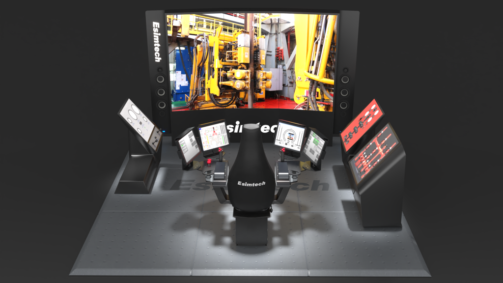
Because of the unique characteristics of the oil drilling industry, the need for a drilling simulator is to save a significant amount of people and resources for drilling training. A petroleum drilling simulator is a type of virtual training equipment that simulates the driller's work in a drilling operation by utilizing modern electronic technology and communication principles.
Esmitech has created a portable drilling simulator that sends operational instructions to the simulation console in order to obtain interactive control of the virtual 3D well pad.
The trainees can operate directly through the driller's console simulator to restore the well site operation process, as if sitting in the driller's control room, with a strong sense of presence and realism, thanks to the combination of simulator and 3D technology.

The Esmitech drilling simulator is portable, easy to transport, and can be used for mobile education. The simulator can create a network-based multi-user shared virtual environment in which users of various types of work training can control their own virtual characters and interact with the virtual characters controlled by others to achieve the goal of simulation training.
Features Of Esmitech Portable Driller Simulator
Control of physical operations
There is no sequenced driller operation mode.
True 3D picture interaction in real time
Sound effect of a realistic environment
Voice prompting in real time
Advanced and precise physical and mathematical models, in accordance with real-world process requirements
Cooperative operation in various sorts of work teams
The training material is methodical and comprehensive, and the project structure is adaptable.
User-friendly UI that is simple to learn

Functions Of Esmitech Portable Driller Simulator
Drilling modes, such as rotary table drilling simulator and top drive simulator, can be selected.
The parameters for beginning the drill can be changed to influence the drill's operation dynamics.
Capable of displaying the well-site image.
Conduct training on a variety of drilling operations, such as tripping out and joining single pipes.
Drilling simulation should be done interactively. The system receives the operation command from the operation console, evaluates its action attribute, and provides feedback.
Esmitech Portable Driller Simulator Operation Projects
The training program essentially covers all drilling procedures, including rotary table drilling and top drive drilling. Patrol inspection, drilling operation, and accident handling are all part of the rotary table and top drive drilling operation modules, respectively.
(1) Rotating drilling operation patrol inspection
The drilling project
1. drilling and joining a single pipe
2. stumbling and falling in the hole
3. casing operation
(2) The accident handling operation can be carried out by the teacher randomly introducing equipment and downhole defects during the well control simulator operation, so that the trainees can learn the judgment and fault handling procedures.

Applications Of Esmitech Portable Drilling Simulator
It can handle downhole accidents like stuck tripping, stuck tripping, high-pressure formation drilling, low-pressure formation drilling, adhesive sticking, sand setting sticking, mud bag sticking, drill pipe suction, well kick caused by high-pressure permeability layer, multiple well kick, lost circulation, underground blowout, out-of-control blowout, out-of-control blowout, and fire.
The Esmitech Portable Drilling Simulator is a versatile tool that can be utilized in a variety of drilling-related tasks. The simulator is commonly used for the following purposes:
Training: The simulator is a fantastic training tool for all levels of drilling operators. It provides a safe and regulated environment for practicing skills and techniques such as drilling, tripping, and well management.
Assessment: The simulator can be used to evaluate drilling operators' abilities and competency. It gives instructors real-time feedback on their students' performance, allowing them to discover areas for development and provide specific comments and coaching.
Research and development: The simulator can be used for drilling-related research and development. It can be used to evaluate the effectiveness of different drilling procedures, as well as detect potential risks and hazards related with drilling operations.
Training for emergency response: The simulator can be used to mimic emergency events such as well blowouts or equipment breakdowns. Drilling operators can practice emergency response methods in a safe and controlled environment.
Reasons Why Buy Drilling Simulator From Esmitech
Pre-job planning: Before implementing drilling plans and procedures in the field, the simulator can be used to develop and test them. This can assist in identifying potential problems or concerns and refining the plan prior to the start of real drilling operations.
The Esmitech portable drilling simulator is a highly advanced and realistic simulator built for drilling operator training and improvement. It has a number of features and benefits that make it an appealing option for individuals looking to improve their drilling skills. Among these traits and benefits are:Portability: The Esmitech Portable Drilling Simulator is small and portable, making it perfect for usage in distant areas or where room is limited.
Realistic simulation: The simulator simulates several drilling scenarios and conditions to deliver a highly realistic drilling experience. This enables workers to hone their abilities in a safe and regulated environment without risk of damaging equipment or causing mishaps.
Customizable scenarios: The simulator enables for the construction of customizable scenarios that can be tailored to the operator's or organization's individual needs and training goals.
Cost-effective: The simulator is a less expensive alternative to typical training methods including on-the-job training or costly drilling courses.
Continuous improvement: Because the simulator gives quick feedback on performance, operators can discover areas for improvement and fine-tune their skills.
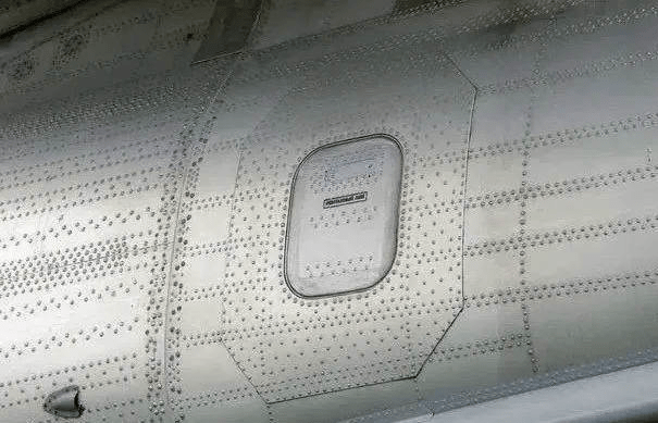
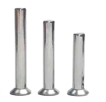
Fasteners are commonly utilized in the aerospace industry. Aircraft wings are typically thin yet extremely strong. When we examine the plane closely, we can observe that there are numerous rivets on the plane's envelope.
A plane has millions of rivets, according to legend. So, why does the airplane use the rivet process instead of welding method? In this article, we will discuss the reasons as following.
1. Welding is difficult.
Engineers utilize the lightest materials feasible in aircraft building to reduce aircraft weight. Aircraft envelopes are often comprised of very thin materials. Welding together envelopes that are too thin is quite challenging. Furthermore, the composite material of the envelope is more vulnerable to welding damage, and the connectivity of different elements must be fixed physically. As a result, rivets are preferable.
2. The material to be welded will generate a lot of heat during flight and welding, and it is not suitable for use in aircraft.
A lot of heat is generated on the surface of an airplane when it is flying at high speeds. Because the temperature of the flying environment varies so much, this phenomena of thermal expansion and contraction will have a significant impact on the integrity of solder junctions.
Some airplane fuselages are built of aluminum, which has a low heat resistance. Because the welding procedure generates a lot of heat during the welding process, it is not suited for aircraft with aluminum fuselages.
3. The airplane has been in a resonance environment for an extended period of time.
Because the aircraft is in a resonance environment for an extended period of time when flying. It is easy to break if welding is applied.
4. Rivets are stronger than welding.
(1) Welding has numerous downsides. Welding, whether thin or thick, may have an effect on the aircraft.
(2) Rivets make the airplane safer, and they also help to reduce resistance in flight.
v(3) Using rivets can significantly cut costs.(4) Rivets are less harmful to the environment than welding.
(5) If the turbulence is severe throughout the flight, the aircraft's wings will swing up and down dramatically. The envelope of the wing is expanded or squeezed throughout the swing. If the welding procedure is employed, the weld's strength will be greatly diminished when subjected to frequent stress variations. These welding spots are likely to develop some minor cracks over time. The weld is prone to metal fatigue after a long period of time.
The rivet connection can decrease the transmission of vibration between the joints, lowering the danger of shock cracking. The firmness is better and more reliable for such repetitive stress variations.
5. Riveting allows for standardized and quantitative output.
The welding quality is mostly determined by the operator's expertise, and the randomness of the welding thickness is very high. It is still challenging to create consistent standards.
The characteristics of the rivets used in the riveting process have relatively tiny mistakes, making quality control and uniform production simple. Rivet machining accuracy is controlled to the micron level.
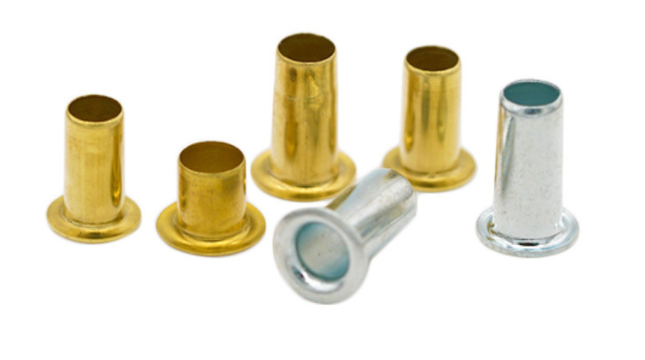
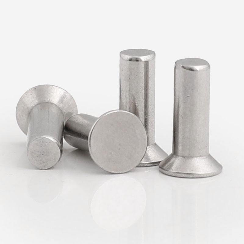
6.Rivets will lower the aircraft's aerodynamic drag during flight.Rivets reduce rather than increase aerodynamic drag. Because the rivets used in the aerospace industry are mostly convex and countersunk. Because there is no demand for aerodynamic design in the interior of the aircraft, convex head rivets with low cost and easy processing are primarily used. Countersunk rivets are mostly employed on the aircraft's exterior, where they can significantly reduce drag. During the milling process, there are rigorous tolerances for the nail cap and adjacent structures.
This application has produced outstanding outcomes. According to pertinent World War II data, the use of countersunk rivets can reduce aircraft resistance by around 3%.
A freeze dryer is a scientific method that pre-freezes water-containing goods before sublimating their moisture in a vacuum state to produce dry items. The freeze-dried items can be preserved for an extended period of time and can be restored to their pre-freeze-drying state while retaining the original biochemical properties after adding water.
Vacuum freeze-drying technique has numerous applications in bioengineering, pharmaceutical industry, food industry, material science, and deep processing of agricultural and byproduct products, and the scale and field are continually developing. To that purpose, vacuum freeze-drying will be a significant application technology in the twenty-first century.

The structure of the Lab freeze dryer
A refrigeration system, a vacuum system, a heating system, and an electrical instrument control system comprise the freeze dryer. The drying box, condenser, refrigeration unit, vacuum pump, heating/cooling device, and so on are the essential components.
The refrigeration system, also known as the "heart of the freeze dryer," is the most critical component of the freeze dryer. Compressor, refrigerant, oil separator, water condenser, filter drier, intercooler, sight glass, solenoid valve, hand valve (top cover valve), expansion valve, evaporation (plate exchanger, rear box condensing coil), vapor-liquid separator, return air filter, pressure gauge, pressure control relay, CPCE (energy regulator), safety valve, refrigeration pipeline, and other components comprise its refrigeration system.

How does Freeze Dryer work?
Freeze drying is a drying process that works on the sublimation concept. It is a method that involves rapidly freezing dry material at a low temperature and then directly sublimating the frozen water molecules into water vapor in a suitable vacuum environment. Freezing The dried product is known as a lyophilizer, and the process is known as lyophilization.
After the liquid refrigerant absorbs the heat of the cooled material in the evaporator, it is vaporized into low-pressure and low-temperature steam, which is inhaled by the compressor, compressed into high-temperature and high-pressure steam, and then discharged into the condenser. It releases heat to the cooling medium (water or air), condenses into a high-pressure liquid, is throttled by a throttling device to a low-pressure and low-temperature liquid, and enters the evaporator again to absorb heat and vaporize.

How do I select a freeze dryer?
Many precise features must be considered while selecting a freeze drier. Customers must purchase a freeze dryer that meets their requirements. When selecting a freeze dryer, examine not only the price, but also the temperature of the cold trap, the cooling rate, the temperature homogeneity of the board, the flatness, and other indicators.
Cold Trap Temperature
A cold trap is a device that traps water during the freeze-drying process. In theory, the lower the temperature of the cold trap, the greater its ability to catch water. The experimental series freeze dryer's cold trap temperature has multiple classes, including -45°C, -60°C, and -80°C. Some items that are easily freeze-dried can benefit from freeze-drying with a cold trap temperature of -45°C. Most items can be freeze-dried using freeze-drying devices with a cold trap temperature of around -60°C. Freeze-drying with a -80°C cold trap temperature It is appropriate for the lyophilization of some specialty items. The influence of cold trap temperature on water-capturing ability was experimentally established, with the water-capturing capacity greatly increased when the temperature of the cold trap dropped from -35°C to -55°C. In the absence of unique requirements, a cold trap temperature of roughly -60 °C is an excellent choice.
Cooling Rate
The cooling rate reflects the refrigeration system's cooling capacity. The temperature of the cold trap shall reach the minimum temperature indicated in the index within 1 hour under no-load conditions. For a freeze dryer with a cold trap temperature of -60 °C, for example, the machine begins timing from the time the machine is turned on for refrigeration, and the time for the cold trap temperature to reach -60 °C should not exceed 1 hour.
Ultimate Vacuum
The final vacuum degree shows the leaking of the freeze drier as well as the vacuum pump's pumping performance. The freeze-drying box's vacuum level. Previously, the higher the vacuum degree, the better. According to contemporary thinking, the vacuum degree should be within a tolerable range. The vacuum degree is too high, which inhibits heat transfer and slows drying, yet the no-load limit vacuum degree of the freeze-drying box should be greater than 15Pa.
Uniformity of plate temperature and flatness
The consistency and flatness of plate temperature have a significant impact on product quality uniformity. The higher the temperature uniformity and flatness, the higher the quality of the freeze-dried product. The temperature of the freeze dryer shelf can be controlled by a heater or an intermediate fluid. The temperature uniformity and flatness of the freeze dryer shelf with an intermediate fluid control layer are excellent. This layer of freeze dryer plate is a hollow sandwich structure. The cooling and heating of the plate are accomplished through the circulation of the intermediate fluid in the fluid channel within the plate, resulting in consistent plate temperature. The fluid in the centre of the shelf technology is used by the freeze dryer. The bell-type freeze dryer's shelf temperature control employs a heater, resulting in slightly poorer temperature uniformity of the plating layer. However, the temperature difference between the layers of the medical freeze dryer should be kept within 1.5 °C, and the temperature difference inside the plate should be kept within 1 °C, and the food freeze dryer can be suitably relaxed.
Summary
We can deduce from the preceding information that different types of laboratory freeze dryers should be used depending on the industry. For many years, DRAWELL has been the most successful freeze dryer producer in China, offering high-quality freeze dryers to laboratories all over the world. Please contact us if your laboratory requires a freeze dryer or other laboratory equipment; we will be your best choice.
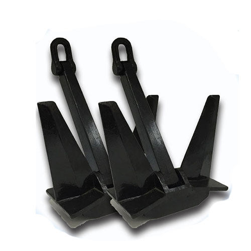
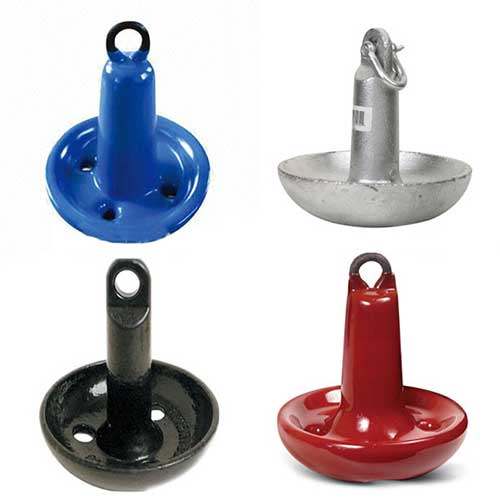
Marine anchors are essential components for keeping marine vessels moored securely. These devices are designed to give the vessel a secure and steady hold on the bottom, preventing it from drifting away due to wind, current, and wave forces.

Principle Of Marine Anchor
The principal purpose of a marine anchor is to create a holding force that keeps a vessel in place while at anchor or moored. The anchor is designed to sink into the seafloor and endure wind, tide, and wave stresses that would otherwise cause the vessel to drift or be damaged. When the anchor is fully set and the chain or rope is taut, it provides a holding force that is transmitted to the vessel.
An anchor's ability to generate a holding force is governed by its design and the resistance it encounters as it sinks into the bottom. The anchor must be heavy enough to sink into the seafloor and withstand the vessel's forces. It must also be able to penetrate the seafloor and take a strong grip.
The chain or rope that connects the anchor to the vessel must be strong enough to withstand the tension and stress induced by wind, current, and waves, as well as the weight of the vessel. The length of the chain or rope is also important since it determines the angle of the anchor as well as the amount of holding force supplied to the vessel.
Explanation of the role of the anchor and chain in establishing a secure hold
The anchor and chain or rope are crucial in generating a stable hold for a moored or at anchor vessel.
For starters, the anchor is the vessel's primary point of contact with the seafloor. Its purpose is to sink into the seafloor and generate a holding force that can endure the forces of wind, current, and waves. Once the anchor is properly embedded in the seafloor, it offers a strong foundation for the vessel's stability.
Second, the chain or rope connects the anchor to the vessel and transfers the anchor's holding force to the vessel. The chain or rope must be strong enough to withstand the tension and stress created by wind, current, and waves, as well as the weight of the vessel. The length of the chain or rope is also important since it determines the angle of the anchor as well as the amount of holding force supplied to the vessel.
A major component that permits a vessel to remain at anchor or moored is the anchor and the chain or rope. Without the anchor, the vessel would be subject to the forces of wind, current, and waves and may be washed away or damaged. Similarly, without a strong and dependable chain or rope, the anchor cannot convey holding power to the vessel, and the vessel cannot remain in place.
What are the Factors that Affect the Sinking Depth and Resistance
The greater the gripping force, the deeper the anchor dives and the greater the resistance. The ideal mix of anchor weight, design, chain/rope length, and anchor type is decided by the operating conditions as well as the vessel's size and weight.
Anchor weight
A heavier anchor sinks further and provides more resistance than a lighter anchor.
Anchor design
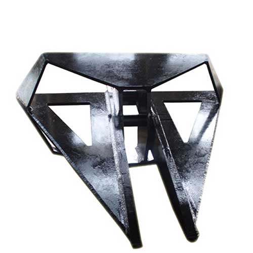
The shape and design of the anchor determine its ability to penetrate and retain in the seafloor. Different designs are better suited to different types of seafloor.
Seabed composition
The composition of the seabed effects the anchor's capacity to penetrate and hold. Soft, muddy seafloors are less resistant to erosion than hard, stony seafloors.
Anchor chain/rope length
The length of the anchor chain or rope determines both the angle at which the anchor sets and the amount of holding force it may generate. The anchor can be positioned at a flatter angle with a longer chain or rope, providing extra holding force.
Water depth
The depth of the water influences the length of the chain or rope required, as well as the amount of resistance that the anchor must provide.
Current and wind speed
The speed and direction of the current and wind influence the stress on the anchor and the amount of resistance it must provide to keep the vessel in place.
Vessel size
The amount of resistance required to keep the vessel in place is affected by its size and weight.
Anchor type
Different types of anchors operate differently in different settings. Some anchors are more effective on sandy or muddy seabeds, whereas others are more effective on rocky seabeds.
How the Holding Force Affected by the Marine Anchor
The holding force created by a marine anchor is a function of its design and the resistance it encounters as it sinks into the seabed. Once the anchor is fully set and the chain or rope is taut, the anchor generates a holding force that is transmitted to the vessel.
1. The surface area of the anchor that makes contact with the seafloor influences the holding force it produces. Anchors with bigger surface areas generate more holding force than smaller surface area anchors.
2. The design of the anchor determines its ability to penetrate the seafloor and generate holding force. Some anchor designs are better suited to soft or muddy seabeds, while others are better suited to rocky seabeds. The angle at which the flukes or blades of the anchor are positioned, as well as their shape, impact the anchor's ability to penetrate and hold.
3. The anchor's holding force is affected by the depth to which it sinks and the resistance it encounters as it sinks into the seafloor. A heavier anchor will generate more holding force than a lighter anchor that dives shallower and encounters less resistance.
4. The length and strength of the chain or rope that connects the anchor to the vessel influence the holding force delivered to the vessel. A longer, stronger chain or rope allows the anchor to be set at a flatter angle, resulting in greater holding force.
Summary
The article describes how marine anchors work, how they are used to secure boats, ships, and other marine vessels, and how the process of sinking the anchor into the seabed and creating the holding force that keeps the vessel in place works.