In a web guiding system, PID control enhances precision, decreases variability, has a faster response time, and is adaptable to different web materials. We will introduce a web guide PID controller and explore its description, operating principle, benefits, applications, and difficults associated with its use in this part.
What is a Web Guide PID Controller
A web guide PID (Proportional-Integral-Derivative) controller is a closed-loop control system that uses sensor feedback to automatically change the location of a moving web material, such as paper, plastic, or fabric, to maintain it aligned with a desired route or edge. The web guide controller constantly monitors the position of the web material and calculates an error signal based on the difference between the desired and actual positions.
The PID controller then changes the output of an actuator, such as a motor or pneumatic cylinder, to correct the position of the web material. To change the output signal depending on the error signal, the rate of change of the error signal, and the integral of the error signal over time, the PID controller employs three control components.
How does a Web Guide PID Controller Work
The operating principle The web guide PID controller is concerned with maintaining the alignment of a moving web material.
The PID controller continuously monitors the position of the web material using one or more sensors. These sensors could be edge guide sensors, line sensors, or other sorts of sensors, depending on the application. Based on the difference between the actual position of the web material and a desired path or edge, the controller determines an error signal.
The PID controller then changes the output of an actuator, such as a motor or pneumatic cylinder, to correct the position of the web material. The actuator could be linked to a guiding roller, a steering roller, or another web handling system component, depending on the specific design.
The Proportional, Integral, and Derivative components of the PID controller are employed in that sequence to change the output signal based on the error signal, the rate of change of the error signal, and the integral of the error signal over time. This enables the controller to make precise and exact adjustments to the position of the web material.
In a web guiding system, the proportional component of the PID controller is typically used to respond quickly to changes in the position of the web material, while the integral component is used to eliminate steady-state errors and the derivative component is used to reduce overshoot and dampen the response to disturbances.
The tuning parameters of the PID controller can be modified to optimize its performance for different web materials, speeds, and other operating scenarios. Depending on the complexity of the web handling system, the web guide PID controller can be configured to operate in single-axis, dual-axis, or multi-axis control modes.

What are the Benefits of a Web Guide PID Controller
Improving accuracy and precision
The PID controller may precisely adjust the placement of the web material, improving the web handling system's accuracy and precision.
Reducing waste
By assuring proper alignment of the web material, the web guide controller helps prevent waste caused by misalignment, wrinkling, or other material faults.
Increasing productivity
The controller can keep the web material aligned at high speeds, boosting the efficiency of the web handling system.
Flexibility
Depending on the complexity of the web handling system, the PID controller can be configured to operate in single-axis, dual-axis, or multi-axis control modes. As a result, it is an adaptable solution for a wide range of web-handling applications.
Adaptability
The web guide controller can adapt to changes in the web handling system, such as differences in web speed, tension, or material characteristics, to ensure precise alignment of the web material.
Reduced operator intervention
The web guide PID controller may run autonomously, reducing the need for user participation and increasing system reliability.
What are the Applications of a Web Guide PID Controller
PID controllers for web guides are utilized in a variety of manufacturing and processing applications where precise control of web materials is required.
Printing
Web guides are used in printing applications. PID controllers are utilized to keep the web material aligned accurately during printing, decreasing waste and enhancing print quality.
Converting
Creating a Web Guide PID controllers are used in converting applications such as cutting or slitting of materials to ensure accurate web material alignment, reduce waste, and improve the quality of the converted output.
Packaging
Web guidelines for packaging are utilized in packaging applications. PID controllers are used to keep web material alignment correct during packaging operations, reducing waste and improving packaged product quality.
Coating
Web guide PID controllers are used in coating applications such as coating films or papers to keep the web material aligned, hence improving the quality of the coated result.
Textile
Web guide PID controllers are used in textile applications to maintain perfect fabric alignment during weaving or knitting operations, hence reducing wastage and improving quality.
Automotive
Web guide PID controllers are used in automotive manufacturing applications to keep materials perfectly aligned throughout processes such as cutting, stamping, or laminating, hence improving the quality of the manufactured automobile components.

What are in Difficults For a Web Guide PID Controller
Non-linear behavior of web materials
Web materials can exhibit non-linear behavior, making it challenging to forecast and control their position. This could induce oscillations or overrun in the control system.
Varying material properties
Thickness, elasticity, and surface characteristics of web materials may influence the behavior of the web handling system. This can make tweaking the PID controller for peak performance difficult.
External disturbances
External disturbances, such as changes in web tension or air drafts, may affect the position of the web material, resulting in mistakes in the control system.
Sensor positioning and precision
The accuracy and location of web guide sensors used to measure the position of the web material can have an effect on the operation of the control system. Inaccurate sensor readings can lead to incorrect control actions.
Maintenance and calibration
The PID controller and its supporting hardware components must be repaired and calibrated on a regular basis to ensure optimal operation. This may need downtime for the web handling system, affecting production timetables.
The technical level of operators directly influences the efficiency of oil and gas operations. Esmitech has released a range of oil simulators to help operators increase efficiency by simulating scenarios. Esmitech is dedicated to increasing the safety and efficiency of the petroleum sector as the world's top provider of drilling simulation technology.
The Esmitech simulator complies entirely with IADC and IWCF requirements, delivering the most stringent industry standards for drilling and well control simulation training. The Esmitech simulator portfolio comprises portable and full-size drilling and well control simulators, as well as complex network base models for specific customer needs.

What is Portable Drilling Simulator?
The portable drilling simulator is extremely practical and can play a huge role in different kinds of operations. Compared with other technologies, its characteristics are very obvious. Using portable drilling simulator, drilling, well control training can be conducted on a single simulator platform, and can be packaged in a customized protective sleeve for transportation.
The module-based learning management system has a user-friendly interface that is easy to operate and use. Esmitech simulator supports human-machine interface system and drilling simulator of various oil drilling rigs to track and report the progress and development of training and simulation operations in a timely manner.
For the performance in training, the evaluation, feedback and improvement functions in simulation can play a significant role in improving. In addition, cloud-based dashboards can be used to remotely monitor the ability of operators. In addition, cloud-based dashboards can be used to remotely monitor the ability of operators.
Advantages of Using Portable Drilling Simulator
Portable drilling simulators can help improve safety by providing workers with a realistic training experience in a controlled setting, allowing personnel to practice procedures and methods without the risk of real-world mishaps.
Savings on equipment and staff: Portable drilling simulators can be a cost-effective alternative to traditional field training, which can be costly due to the need for specialized equipment and personnel.
Portable drilling simulators can provide workers with a realistic and engaging learning experience, helping to enhance learning outcomes and retention rates.
Portable drilling simulators can be used to standardize training across different locations and teams, ensuring that everyone is trained to the same level and using the same methodology.
Portable drilling simulators can help boost productivity by minimizing the time necessary for on-the-job training and allowing workers to become adept in their abilities more rapidly by allowing workers to practice processes and techniques in a virtual environment.
Portable drilling simulators can be an effective tool for enhancing drilling and well control safety by providing workers with a realistic and engaging training experience that eliminates the need for expensive and time-consuming field training.
How Portable Drilling Simulator Used For Improving Operation Efficiency In Petroleum Industry
Portable drilling simulators can help the petroleum sector enhance operational efficiency in a variety of ways. Some examples are:
Portable drilling simulators can provide workers with a realistic and engaging training experience, which can aid in improving learning outcomes and retention rates. This can help people become more skilled in their abilities faster and reduce the amount of time necessary for on-the-job training.
Portable drilling simulators can be used to standardize training across different locations and teams, ensuring that everyone is trained to the same level and using the same methodology. This can help increase operational consistency and reduce the likelihood of errors and mishaps.
New technology testing and evaluation: Portable drilling simulators can be used to test and assess new technologies such as automation systems and remote monitoring tools. This can help companies identify ways to improve efficiency and reduce costs in drilling and well control operations.
Virtual drills and simulations can be conducted using portable drilling simulators, allowing workers to practice emergency response protocols in a safe and controlled setting. In the event of an actual disaster, this can help increase readiness and reaction times.
Portable drilling simulators can be used to test worker performance and indicate areas where more training may be required. This can assist businesses in identifying areas for improvement and ensuring that employees are functioning at their best.
Companies in the petroleum industry can increase operation efficiency and decrease the risk of accidents and downtime by employing portable drilling simulators to improve training, evaluate new technologies, and analyze worker performance.
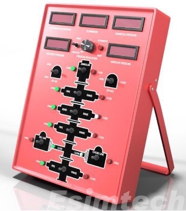
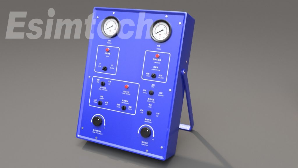
ESIM-PDS9B Portable Drilling Simulator
The real-time portable drilling simulator trains drill rigs on drilling operations, equipment control, well control, and crane operation. The interactive device's non-teacher mode and the long-term provision of training, development, and evaluation are fundamentally redefining the drilling industry's training mode. The operators can create and perform drilling and well control exercises, as well as display downhole conditions in 3D images. This allows learners to see and understand the repercussions of their actions, as well as the ramifications of the same actions in different drilling operations.
Advantages
Economy: by allowing unlimited team practice, you may maximize your return on investment.
Ensure that the team is well-trained and capable, and that it adheres to internationally accepted standards.
Reality: providing hands-on training without endangering assets, workers, or the environment.
Interactivity: make team training easier and more interactive through four consoles.
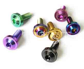
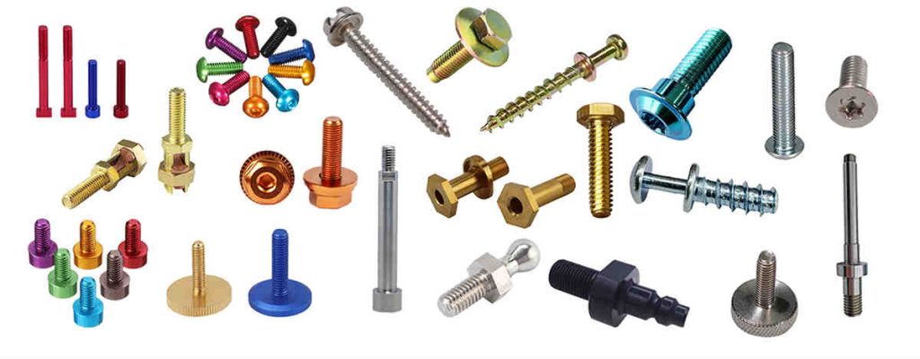
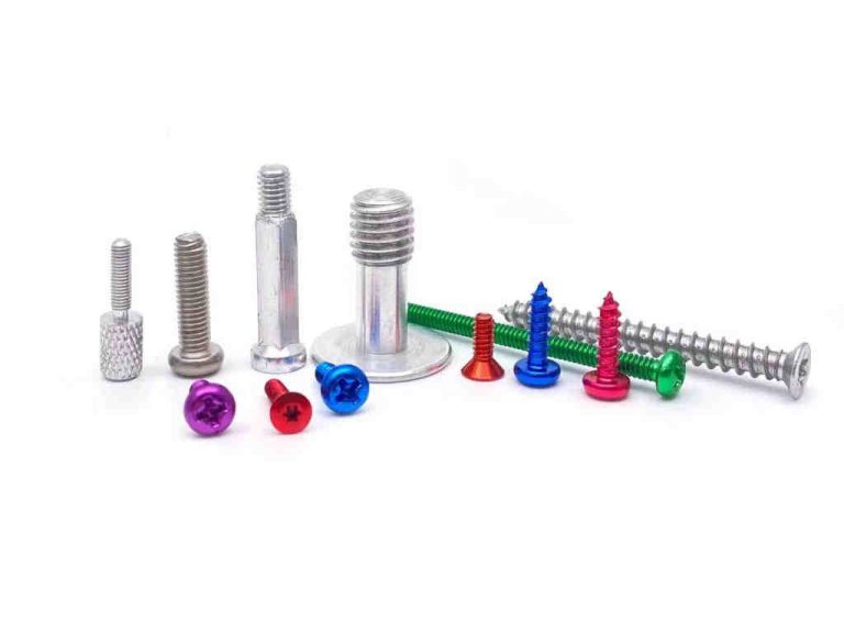
Screws are brightly colored. Screw fasteners of various colors, such as silver, black, yellow, purple, and so on, can be found everywhere. So, how did these multicolored screws come to be? Screw plating is a procedure that adds vibrant colors and beauty to screw fasteners.
Screw plating is used for colored products
The screw is quite greasy and unclean when it is freshly manufactured. At this moment, it must be brought to an electroplating plant to be made attractive and functional. The color of the screw electroplating can be matched with the color of the material. When a screw fastener is plated, it takes on a more colorful and bright appearance.
Screw plating is available in white zinc, blue zinc, colorful zinc, white nickel, black nickel, black zinc, and green.
What should be paid attention to during the screw plating process?
1. If screws with different specifications mix together for electroplating, some areas cannot be plated, resulting in product scrapping. Before electroplating, the screws must be cleaned.
2. It is difficult to achieve the quality requirements of electroplating layers and diverse specifications, such as the appearance color and screw properties, under the process conditions of conventional electroplating, most of which require professional operation.
3. Screw specs are too near, for example, the size and length appear to be the same. This type of screw plating should be done separately; otherwise, it is difficult to screen.
4. Plate heavier screws and lighter screws separately. To electroplate, smaller and larger screws should be separated. Otherwise, screws of various specifications and models become locked together during the electroplating process, causing harm to the screw.
5. The screws are easily electrocuted when they become trapped together. Otherwise, the two distinct specifications and models of screws become entangled, which quickly leads to plating failure, even after the screw plating has been completed. It is also difficult to separate different types of screws.
Quality control methods of screw plating product
The key measurement standard for screw plating quality is corrosion resistance and attractiveness. The corrosion resistance is designed to mimic the product's environment. Set the test settings to the environment and conduct the corrosion test. So, what are the quality assurance procedures for screw electroplating products?
1. Appearance
The screw's entire surface must be coated. Scorching, roughness, grayness, peeling, crusting, visible stripes, pinholes, loose passivation film, cracking, and severe passivation traces are not permitted.
2. The thickness of the plating
In a corrosive environment, the service life of a self-tapping screw is directly proportional to the plating thickness. Hot-dip galvanized has an average thickness of 54um and a minimum thickness of 43um.
3. Distribution of plating
The plating aggregation technique on the fastener surface differs. The plating metal is not consistently deposited on the edge of the outer peripheral while plating. To achieve a thicker plating at the corner, various accumulation processes are used. The screw's thickest plating is at the top of the thread, gradually becoming thinner at the front of the thread, and thinnest at the bottom. Hot dip galvanizing is the polar opposite. The inner corner and bottom of the thread receive thicker plating. Mechanical plating has the same metal accumulation propensity as hot dip plating, but it is considerably smoother and the thickness of the overall appearance is much more consistent.
4. Emrittlement due to hydrogen
When fasteners are processed, particularly during the pickling and alkaline processes before to plating and subsequent electroplating, the appearance absorbs the hydrogen atom, and the accumulated metal plating captures hydrogen. When the screw is tightened, the hydrogen moves to the most concentrated region of the stress, causing the pressure to rise to levels that exceed the strength of the base metal, resulting in a little appearance fracture. Hydrogen is especially aggressive and quickly enters into newly created cracks. This cycle will continue until the fastener snaps. It usually happens within a few hours of the first stress. To reduce the risk of hydrogen embrittlement, the fastener should be heated as soon as possible after plating to allow the hydrogen to be expelled from the plating. The heat treatment is normally performed for 3-24 hours. Mechanical galvanizing is non-electrolyte, hence the threat of hydrogen is eliminated.
Summary
Screw plating gives fastener products vivid colors, making them beautiful, colorful, and gorgeous. What should be paid attention to throughout the electroplating process and how to control the quality of the screw products are major concerns. The article provides some important information for improving the effect of screw plating.
High performance liquid chromatography (HPLC) is one of many test devices used in laboratories. The apparatus is based on classical chromatography, using gas chromatography theory, and technically converts the traditional mobile phase to high-pressure delivery. This article will explain the failure causes and treatment methods of high-performance liquid chromatography (HPLC), as well as its properties, working principle, applications.

How Does High Performance Liquid Chromatography Work?
The mobile phase enters the system by a high-pressure pump, the sample solution enters the mobile phase via a syringe, and the mobile phase is loaded into the chromatographic column (stationary phase) in HPLC chromatography. However, the moving speed of each component after repeated adsorption-desorption distribution in the two-phase sample solution is significantly varied due to the variable distribution coefficients of each component in the two-phase sample solution. It is broken down into a single component that exits the column. As the sample concentration passes through the detector, it is turned into an electrical signal that is supplied to the recorder, and the data is recorded as a graph.
Applications of High Performance Liquid Chromatography
High-performance liquid chromatography (HPLC) is an instrument that uses the principle of high-performance liquid chromatography to examine organic molecules that have high boiling temperatures, are non-volatile, are thermally unstable, and have large molecular weights. It is made up of the liquid storage tank, the pump, the injector, the chromatographic column, the detector, the recorder, and other components. Life sciences, food sciences, pharmaceutical research, and environmental research all make extensive use of HPLC.
1.It can be used to analyze cyclic aromatic hydrocarbons (PAHs), pesticide residues, and other environmental contaminants.
2.It may be used for food nutrition analysis, food additive analysis, food contaminant analysis, and so on.
3.Purification, separation, and determination of molecular weight compounds can be examined at the molecular level in life science, genetic engineering, clinical chemistry, molecular biology, and biochemistry.
4.Application in the medical examination: metabolite analysis and determination in body fluids, pharmacokinetics, clinical medication monitoring, and so forth.
5.Inorganic analysis: examination of anions and cations, for example.

Common Faults and Treatment Methods of High Performance Liquid Chromatography
Fault 1: There are bubbles in the mobile phase; turn off the pump, open the exhaust valve, press the cleaning button, and open the vent; the bubbles continue to emerge from the filter and enter the mobile phase, regardless of how many times the cleaning button is turned on; it cannot be cleared continuously. produced air bubbles.
The cause and how to deal with it: The filter has been drenched in water for an extended period of time, and as a result of mold growth and spread in the filter head, the filter has become clogged by the production of bacteria.The buffer has a tough time passing smoothly through the filter head, and the air flows through the filter under pump pressure and enters the mobile phase.
The filter head was immersed in 5% nitric acid solution for 15 minutes before being ultrasonically cleaned. The filter head can also be soaked in 5% nitric acid solution for 12 hours, shaken gently for 36 hours, rinsed several times with pure water, open the exhaust valve, open the purification key, and remove the gas from the filter tank; if there is still gas in the filter bubbles, soak the filter in 5% nitric acid solution for another 12 hours.
If no bubbles continue to occur in the filter, it implies that the mold in the filter can be killed by nitric acid, and the mobile phase may pass smoothly through the filter. Open the exhaust valve, adjust the pump flow to 1.0 30 mL/min, and rinse 1 The filtrate can be cleaned after about an hour. Close the pressure-reducing valve and flush for 30 minutes with pure methanol.
Fault 2: excessive column pressure
The reason behind this and how to deal with it:
(1) In the column, buffer salts such as ammonium acetate, etc. are deposited;
(2) Deposition of sample contamination
Fault 3: There is no indication of pressure or liquid flow.
The reason behind this and how to deal with it:
The pump sealing gasket has worn; a substantial volume of gas has entered the pump body: handle the first situation by replacing the sealing gasket.
In the second situation, utilize a 50 mL glass syringe at the pump output without assisting in air extraction while the pump is turned on.
Fault 4: The pressure varies dramatically and the flow is unsteady.
The reason for the failure and the technique of treatment: There is a foreign body between the gem ball and the air seat or one-way valve, preventing the two from being sealed together.
Pay attention to the amount of mobile phase produced while working, ensure that the stainless steel filter sinks to the bottom of the liquid storage bottle, avoid inhaling air, and deflate completely when moving. If there is foreign matter between the check valve and the valve seat, for example, remove the check valve and replace it. Ultrasonically clean it in an acetone-filled beaker.
The information presented above is a DRAWELL overview of the high-performance liquid chromatography (HPLC) principle, application, characteristics, failure reasons, and treatment procedures. I hope you found this essay useful.
Many issues can arise when using high-performance liquid chromatography. If the operator understands the root reason of the failure, it can be avoided and eradicated, and the instrument can be used to its full potential.
Of course, if you're wondering where to acquire an excellent HPLC, I recommend DRAWELL's HPLC. As China's leading provider of high-performance liquid chromatography, DRAWELL offers superior HPLC detection capabilities as well as a very competitive HPLC price advantage, making DRAWELL's chromatography the first option for many laboratories worldwide.
Web guide sensors are industrial devices that track the position of a moving web of material such as paper, film, or foil. They are frequently used in web-processing machines to keep the web centered and aligned during the manufacturing process.
Operation Principle of Web Guide Sensors
Web guide sensors measure the lateral position of the web as it moves through a machine. Infrared edge sensors typically use an infrared light source and a receiver to detect the web's edge. The sensor continuously monitors the location of the edge as the web moves and sends a signal to the control system if any deviation from the desired position is detected.
Why The Web Guide Sensors Are Important In Various Industrial Applications
The control system receives data from the web guide sensors and adjusts the position of the actuator, causing the web to move into the appropriate position. They are critical in ensuring that industrial operations involving the movement of material webs are efficient, dependable, and create high-quality products.
Common Types Of The Web Guide Sensors
There are several different types of web guide sensors available on the market, each with its own strengths and weaknesses.
Ultrasonic sensors
Ultrasonic edge sensors use sound waves to identify the web's edge. Because they are unaffected by liquids or debris, they are especially useful in applications where the web may be damp or unclean.

Infrared Edge Sensor
The Infrared edge sensors are specifically intended to read the edge of webs with sound-transparent, thick weaves, and non-transparent properties. The light source for the web guide sensor is an infrared LED.

Sensors with capacitive coupling
They work by detecting capacitance changes caused by the web's presence. Because they are extremely sensitive and accurate, they are a popular choice for applications needing fine web alignment.
Optical sensors
Optical sensors detect the web's edge by using light. They are simple to install and use, and they have a wide range of uses.
Web Guide Sensors Are Integrated with A Web Guiding System
A web guide sensor is typically integrated into a web guiding system that also includes a control system and an actuator. It is a crucial component of a web navigation system. The sensor's output is used by the control system to alter the position of the actuator, which in turn moves the web into the necessary position.
Web guide sensors can help to decrease waste and improve overall efficiency while also improving web alignment. They can help to prevent faults like wrinkles or creases, which can lead to product waste or downtime, by keeping the web centered and aligned.
Summary
Web guide sensors are a must-have tool for any industrial application that involves the processing of moving material webs. Whether you're making paper, film, or foil, they can help you enhance product quality, reduce waste, and increase overall efficiency.