The oil and gas industry is one of the most important in the world, supplying transportation fuel and energy to industries. However, as oil and gas wells age, their output often decreases, necessitating maintenance or intervention to boost performance. This type of intervention or maintenance is referred to as a "workover" in the oil and gas sector. Workover is the process of increasing or restoring the productivity of an oil or gas well by maintenance, repair, or stimulation activities.
Oil and gas industry rely on advanced technologies such as Downhole Operation Simulator (DOS) software to undertake workover operations. DOS replicates downhole operations, allowing oil and gas engineers to test and optimize interventions before putting them into action in the field. This technology has become a must-have for oil and gas firms, assisting them in lowering the risks, costs, and downtime involved with workover operations.
In this article, we will explain the concept of workover in the oil and gas industry, why workover is required, and the advantages of employing a DOS for workover activities. We will also look at the many sorts of workover procedures and the approaches used to improve their efficiency. The goal of this paper is to provide a comprehensive understanding of workover in the oil and gas industry and the importance of downhole operation simulator for the workover.

Overview of Oil and Gas Workover
Workover Definition
Workover in the oil and gas industry refers to the process of performing maintenance, repairs, or stimulation on an existing wellbore in order to increase productivity or restore integrity. Workover operations are typically performed when a well's production is declining or mechanical difficulties require addressing.
Workover Process
A multitude of steps are involved in the workover process, including well evaluation, design, planning, execution, and evaluation. The well evaluation process entails examining the well's condition, identifying problems, and selecting the best way to remedy them. The design process entails creating a detailed plan for the workover operation, including the necessary equipment, supplies, and employees. The planning stage entails coordinating and scheduling the operation's resources. The execution step involves carrying out the workover operation, including the installation of new equipment, repairs, and maintenance. Finally, the evaluation step involves assessing the effectiveness of the workover operation and making any necessary adjustments.
Workover Types
There are three types of workover operations: remedial, completion, and recompletion. Remedial workovers are undertaken to restore the productivity of an existing wellbore that has had mechanical faults or other production challenges. Completion workovers are performed on newly drilled wells to ensure they are ready for production. Recompletion workovers entail modifying the completion design of an existing wellbore in order to increase its productivity.
Challenges of Oil and Gas Workover
Workover Difficulties and Risks
Workover operations can be dangerous and difficult due to a variety of reasons such as wellbore conditions, well pressure, equipment failure, and weather conditions. These factors can enhance the likelihood of an accident, which can result in personnel injury, equipment damage, or even death. Furthermore, workover procedures can be time-consuming and costly, resulting in lower profitability for operators.
Workover Costs and Productivity
Workover operations can be costly, particularly when dealing with complicated challenges that necessitate the use of specialized equipment and expert employees. Workover activities might incur costs such as equipment rental, personnel, and materials and supplies. Effective workover operations, on the other hand, can increase well productivity and extend the life of the well, resulting in higher profitability.
Workover Safety and Quality
Workover operations necessitate a high level of safety and quality control in order to be carried out appropriately and safely. To protect workers and equipment, operators must follow safety norms and standards. Furthermore, quality control methods must be in place to verify that the workover operation is carried out accurately and produces the required results.
Simulator Concept and Classification
Simulator technology involves the use of computer-based models to simulate real-world scenarios and predict their outcomes. In the oil and gas industry, simulators can be used to predict well performance, optimize drilling operations, and improve workover operations. Simulators can be classified into three main categories: physical simulators, mathematical simulators, and hybrid simulators.
Simulator Design and Development
Simulators are built using specialized software and hardware to imitate real-world circumstances and scenarios. Simulators employ computer languages such as Python and MATLAB, as well as hardware such as sensors, actuators, and controllers.
Applications and Benefits of Simulators
Simulators are used in the oil and gas industry for a variety of purposes, including well performance prediction, drilling optimization, and workover planning and execution. The benefits of employing simulators include lower costs, higher safety, efficiency, and better decision-making.
Downhole Operation Simulator
Components of the System and Functional Features
DOS systems are made up of numerous parts, including software, hardware, and sensors. DOS systems employ software to model the downhole environment and the behavior of fluids and materials within the wellbore. Sensors that measure pressure, temperature, and other downhole characteristics, as well as controllers that regulate equipment performance, are utilized in DOS systems. Downhole operation simulators provide the ability to simulate various wellbore scenarios, optimize workover operations, and provide real-time input on downhole conditions.
Case Studies and Effect Evaluation
DOS technology has been employed in a variety of oil and gas sector applications, including work planning and execution, failure diagnosis and management, and work optimization and improvement. DOS technology has been proved to increase the efficiency and efficacy of workover operations while also lowering costs and improving safety.

Applications of Downhole Operation Simulator in Oil and Gas Workover
Work Planning and Execution
DOS technology can be utilized to simulate multiple wellbore scenarios and optimize workover operations during workover planning and execution. Operators can detect possible issues and design more effective workover plans by mimicking the downhole environment. DOS technology can also be used to instruct workers on workover procedures and to improve their skills.
Failure Diagnosis and Handling
DOS technology can be utilized in failure diagnosis and handling to pinpoint the source of downhole problems and devise efficient solutions. Operators can discover the reason of a breakdown and develop a plan to rectify it by mimicking downhole circumstances. Furthermore, DOS technology can be used to monitor downhole conditions in real time and change equipment to alleviate problems as they emerge.
Work Optimization and Improvement
DOS technology can be used to optimize workover operations and improve well performance. By simulating different scenarios, operators can identify the most effective solutions to improve well productivity and extend the life of the well. Additionally, DOS technology can be used to monitor downhole conditions and make adjustments to equipment to optimize well performance.
Conclusion
Contributions and Research Findings
DOS technology has been proved through research to considerably improve the efficiency and efficacy of workover operations in the oil and gas industry. DOS technology has been proved to lower costs, increase safety, and boost worker productivity.
Limitations and deficiencies
One disadvantage of DOS technology is that it necessitates the use of professional staff who are familiar with the system's software and hardware. Furthermore, DOS technology can be costly to adopt, particularly for smaller businesses.
Directions for Future Development and Research
Future DOS technology research should concentrate on improving system usability and lowering expenses. Furthermore, research should concentrate on the development of new uses for DOS technology, such as wellbore stimulation and enhanced oil recovery.
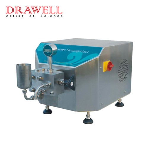
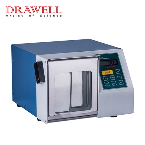
High-pressure homogenizer HPH is an online dispersion machine with excellent efficiency, energy savings, and continuous ultrafine emulsion generation. In contrast to other IKA in-line equipment, the HPH's dispersing action is not based on the rotor/stator principle. Self-decompression of the liquid from up to 2000 bar to ambient pressure improves homogenization in the homogenizer.
Drawell high-pressure homogenizer HPH uses the same amount of energy as standard gear ring dispersers while producing more acceptable emulsions. High-pressure homogenizers are advised for disintegration down to the nanoscale; nevertheless, these homogenizers achieve lower flow rates than traditional dispersions.
How to Use a High Pressure Homogenizer?
1. Installation
Install the high-pressure homogenizer on a flat and sturdy desktop, then one by one install the high-pressure pump, homogenizer valve, pressure gauge, check valve, sample tank, and other components (each component is relatively independent and can be disassembled and installed independently).
Prepare an air compressor or nitrogen tank and circulate cooling water at the same time. The air compressor or nitrogen tank is used to supply the minimum pressure (5-10bar) required by the dynamic homogenization valve, as well as the pressure when the pipeline is flushed and the circulation cooling. When the sample is chilled, water is employed as a cold supply to guarantee that the sample maintains a low temperature during the homogenization process, avoiding sample denaturation and inactivation.
2. Cleaning and Disinfection
Before beginning the machine, inspect the complete sample path to confirm that the tubing is clean. Remove all components from the entire sample channel, then rinse with pure water, then 0.5M NaOH for a short period, and finally warm water.
After cleaning, each component can be sterilized with hot steam, and the pipeline can be sanitized for about 10 minutes after installation using a hot steam cycle.
3. Operation
Before starting the homogenizer, inspect the homogenized liquid to ensure that it is free of contaminants. Impurity particles, particularly metal particles, will harm the pipeline and the homogenizing valve, reducing the homogenizer's service life.
Examine the high-pressure homogenizer's pipeline to confirm that all components are correctly mounted and sealed, and that all bolts are securely fastened. Check the air supply (compressor or nitrogen tank, for example) to ensure that the needed pressure is available; Check the cooling water to ensure that the cooling circulation water was produced ahead of time in accordance with the process requirements, and that the cooling water pipeline was connected.
The small amount of liquid remaining in the pipeline is entirely drained before the HPH of the high-pressure homogenizer begins to work, and the sample is placed into the sample tank and pre-homogenized twice under air pressure.Then, depending on the job needs, increase the homogenization pressure and begin homogenization. Following the completion of the homogenization, the pressure is decreased to zero and the substance liquid is discharged.
4. Maintenance
Immediately after homogenization, rinse with warm water and 0.5M NaOH in a cycle, followed by a rinse with clean water. It can be adequately aerated and pressured during this operation to speed up the cycle and rinse the pipeline more quickly and thoroughly. To finish the cleaning process, rinse 1-2 times with 50% alcohol.
Fill the sample tank and tubing with 70% alcohol solution for the next use after cleaning. If the entire pipeline needs to be sterilized, a hot steam cycle for around 10 minutes is used after the cleaning is finished.
Finally, switch off the power, turn off the air source and cooling water, and so on.
Precautions for Using High Pressure Homogenizer
1. Homogenizing pressure
The homogenization pressure of the high-pressure homogenizer is determined by the material and liquid properties. To minimize unexpected pressure changes, the pressure should be progressively increased during the process of increasing the pressure.
The material homogenization pressure should normally not exceed 2000bar during the homogenization process. To a certain extent, the high-pressure homogenizer allows for overload operation. For a limited period of time, the equipment can operate at 20% overpressure. The control box circuit will then immediately activate the cut-off protection mechanism, which will stop the machine from running. It can be turned back on and work after 30 seconds.
If the pressure cannot rise during the homogenization process, it means that the upper one-way valve is blocked, just use a thin iron wire to pass the ball valve.
2. What Should You Do If the Sample in the High-Pressure Homogenizer Has Air Bubbles?
A high-pressure homogenizer equipped with a dynamic homogenization valve enables the sample to contain air bubbles or to be emptied.
When the sample contains air bubbles or is empty, the homogenizing valve stem and valve seat will clash to some amount during the homogenization process, causing significant wear on the valve stem and valve seat, especially for the manually adjusted homogenizing valve, not only during the homogenization process but also thereafter. It is simple to wear down the homogenizing valve and even directly lead to its fragmentation, rendering it inoperable. Furthermore, it will generate a lot of noise during the homogenization process.
The dynamic homogenizer valve will reduce its damage and noise better, but it is generally recommended to avoid the long-term use of samples containing a large number of air bubbles and the occurrence of empty samples in the pipeline, which can effectively prolong the service life of the homogenizer valve.
3. What Should You Do If Liquid Leaks From the High-Pressure Homogenizer?
There are no o-rings or gaskets in the high-pressure homogenizer's whole sample route, and all face seals are precision-machined metal-to-metal or metal-to-ceramic seals that do not leak liquids.
However, if it is installed incorrectly, if the sample tank and one-way valve are not entirely buckled, or if a component is not properly installed after disassembly, liquid leakage will occur. At this point, all that remains is to inspect the pipeline and install each component appropriately in accordance with the installation manual's specifications.
If the sample is poisonous and harmful, it will endanger and pollute the operating environment and operators. In this case, the above phenomenon can be avoided by simply tightening the sample tank and then flushing the sample passage with air and pressure.
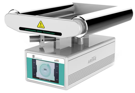
In manufacturing operations across various industries, web guide systems play a crucial role in ensuring precise alignment and material control. However, when it comes to selecting and implementing online directing systems, different types of materials require specific considerations. This article explores the applications and key factors to consider for web guiding systems in connection to various material types.
Web Guide Systems for Paper and Printing Materials
In the paper and printing industries, web guide systems are extensively used to maintain proper alignment and tension of paper and other printing materials. These systems are vital in achieving accurate registration, reducing waste, and enhancing overall print quality. When selecting web guide equipment for this application, factors such as the sensitivity of paper to tension fluctuations, web width, and the need for high-speed and precise registration control should be taken into account. Additionally, the web guide control system should be capable of accommodating different paper grades and sizes, as well as variations in coatings or finishes that may affect the surface characteristics of the material.
Web Guide Systems for Films and Flexible Packaging Materials
Web guide systems are critical in the flexible packaging industry to ensure proper film alignment during printing, laminating, and slitting operations. Films used in flexible packaging can vary in thickness, elasticity, and surface properties, posing unique challenges for web guiding. Elasticity, which affects the gripping and guiding mechanisms of the web guiding system, is particularly important in this application. Moreover, the system should maintain precise tension management to prevent film stretching or wrinkling during the guiding process.
Web Guide Systems for Nonwoven Materials
In nonwoven production, Web guide control systems are employed to align and manage materials such as spunbond, meltblown, and composite nonwovens. Nonwoven fabrics are often delicate and require sensitive handling and precise control to avoid damage or misalignment. Considerations for web guiding systems in this application include the delicate nature of nonwoven materials, the need to minimize contact to avoid distortion, and the ability to handle varying material widths and thicknesses.
Web Guide Systems for Metal Foils and Sheet Materials
Web guiding systems are used in sectors like metal processing and packaging to guide and control metal foils and sheet materials during manufacturing processes. Metal foils can be rigid, necessitating robust guiding mechanisms for proper alignment. In this application, web guide control systems must consider the stiffness and surface properties of metal foils, which may require specific guiding mechanisms and robust control systems. The system should provide precise tension management and be capable of handling variable material thicknesses and widths.
Web Guide Systems for Textiles and Fabrics
In textile manufacturing, web edge guide systems are employed to align and manage fabrics during weaving, printing, and finishing activities. Fabrics can vary in thickness, flexibility, and weave patterns, requiring adaptable guiding devices and accurate tension control. Web guide systems for textiles should incorporate flexible guiding parts to accommodate different fabric widths and patterns. Precise tension control is crucial to ensure proper alignment and prevent fabric distortion throughout the guiding process.
Web Guide Systems for Composite Materials
Web guide systems are utilized to maintain proper alignment during the layup operations involved in fabricating composite materials such as carbon fiber sheets or fiberglass laminates. Composite materials often require careful handling and precise alignment to maintain structural integrity. Special considerations for web guiding machines in this application include regulated tension, gentle handling, and low distortion during guiding. The system should deliver precise and customizable guidance to handle variable material widths and ensure proper alignment during the layup process.
Web Guide Systems for Adhesive Tapes and Labeling Materials
Web guide control systems are necessary in the production of adhesive tapes and labels to ensure perfect alignment and tension control. Accurate registration and consistent alignment are crucial for ensuring the quality and reliability of adhesive products. In this application, web guiding equipment must offer precise registration, minimize waste, and provide reliable edge detection for consistent guiding of narrow webs. The system should be capable of delivering precise guidance to handle varying web widths and maintain exact alignment throughout the manufacturing process.
Web Guide Systems for Foam and Foam-based Materials
In the foam material manufacturing industry, web guiding systems are employed to ensure perfect alignment and tension control during cutting, slitting, and laminating operations. Foam materials can be compressible, requiring specialized guiding systems capable of delicate handling. Compressibility and flexibility are important considerations for web alignment systems in this application. The system should provide precise and gentle web guiding to prevent material distortion or damage during the process.
Summary
Web guide systems are indispensable in industries dealing with various material types. Understanding the applications and unique considerations for each material type is crucial in selecting the appropriate web guiding machine. Carefully considering factors such as material properties, web width, tension control needs, and alignment precision is essential for achieving optimal performance and productivity in material handling and manufacturing operations. By choosing the right web guiding system for a specific material, industries can enhance quality, productivity, and overall production performance.
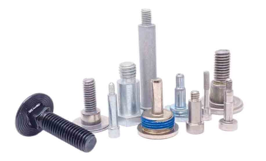
With the development of the automotive industry, the requirements for automotive fasteners have become higher and higher. The main kind of high-intensity automotive fasteners is bolts which all need to be treated with heat treatment to improve the comprehensive mechanical performance of the product and achieve the specified tensile strength. Heat treatment process technology is the key factor in the production of automotive fasteners.

Factors affecting heat treatment process of automotive fasteners
Heat treatment equipment
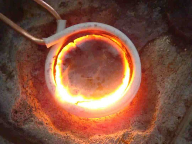
The continuous mesh radiant-tube furnace is most widely used. It has the advantages of uniform heating, stable quality, good working environment, reducing collision of parts, less gas consumption, and small energy consumption.
According to the requirements of the process, dephosphorization function can be added on the cleaning equipment of production line, to remove the phosphorurative layer of the fastener surface before heating. For large size high-strength bolts, to prevent quenching distortion, the UNICASE series mult-purpose chamber furnace should be adopted to heat treatment process.
The heat treatment process of continuous mesh radiant-tube furnace production line: loading-cleaning-heating-quenching-cleaning-tempering-coloring-rolling out, can realize carbon potential control and automatically working.
Heat treatment raw material
The mostly automotive fastener is made of carbon and alloy steel. In addition to the high -intensity hexagonal bolt, according to the GB/T1231 requirements, the materials with specifications below m30 are specified, the other bolts are not clearly specified in international standards. It is only a guide to indicate the alloy elements to be added.
Control methods of heat treatment process for automotive fasteners
The principle of heat treatment process
For the products with the same materials, when the size of the section is different, the quenching degree is different. Although the same quenching and tempering process is adopted, its mechanical properties are different. The larger the cross -section is, the worse the quenching ability is, and the worse the mechanical properties are. At the same time, the same raw materials allow their chemical composition to fluctuate within a certain range. Especially carbon steels will vary from steel mills as the different smelting technology and standards. The finished products produced by the same process must have performance differences.
The quenching heating temperature is mainly determined according to the chemical composition of the steel which is the main factor and the specific process. According to the different quenching medium, the quenching heating temperature is also different.
Due to the comprehensive effect of the organizational stress and thermal stress, the maximum tensile stress will be located near the surface of the parts, which may cause hardening crack. This size is related to the used quenching medium. For the bolts, the diameter of water quenching is 8-10mm and the diameter of oil quenching is 20-39mm. When the bolts in dangerous diameter are quenched, appropriate measures must be taken to prevent hardening crack.
Hydrogen relief treatment
The energy saving and lightweight development of automotive industry has high requirements for the engine design and dynamical system, which includes weight reduction and highly strengthened of bolts and nuts. But as the intensity increases, the fracture caused by hydrogen embrittlement has become a very prominent problem. During the heat treatment process, hydrogen relief treatment must be performed.
Tempered martensite is most sensitive to hydrogen embrittlement. Therefore, the heat treatment process can be adjusted to reduce the generation of Tempered martensite structure.
To prevent hydrogen embrittlement, the high -strength fastener under 1000-1300MPa must be done hydrogen relief treatment after the electroplating. During hydrogen removal, the fastener is heated to a certain temperature and maintains for a period of time and the hydrogen in the material will gather is to form hydrogen molecules. There are two main reasons for incomplete hydrogen removal. One is that there is no timely hydrogen removal, and the other is that the hydrogen removal time is too short.
Strengthen the measurement of fastener center structure
During the heat treatment process of automotive fasteners, as the effects of factors such as quenching heating temperature, quenching ability of materials, and quenching cooling speed will produce ferritic structure in the center of the fastener. Too much ferritic structure will reduce the hardness and strength of the bolt and affect the applications of fasteners. In actual production, For bolts with a large amount of ferrite in the center, when the hardness of the center structure is lower than the product requirements, the improvement of tensile strength is often adopted to control the quality of the product.
In order to control the heat treatment quality of the automotive bolt, it is necessary to measure the ferrite content in the center part of bolts, checking the hardness of the head or tail after quenching and tempering respectively.
What should be paid attention to for heat treatment process of automotive fasteners
Adopting non annealing cold heading steel, non-quenched and non-tempered steel
In order to ensure the performance of cold forming for the automotive fastener, cold heading steel needs spheroidizing annealing in advance, adjusted through the chemical composition of the steel. During the rolling process, the rolling and cooling are controlled to reduce the deformation resistance in the process of cold forming.
Improving the technical documents of thermal treatment process
The heat treatment process is a special process that can’t ensure the quality of the product through subsequent inspections and testing. Therefore, it must have a reasonable system to achieve its control. First of all, identify the factors that may cause process failure, and do a good job of formulating heat treatment process technology. Secondly, establish a comprehensive heat treatment process management system with the documents which clearly indicates the operation methods, process parameters and inspection methods. At the same time, it should be particularly emphasized in the furnace loading method and the batch of furnace and test the raw materials and process conditions of fasteners before heating. It should adopt statistical technology to analyze, calculate and measure the heat treatment parameters, and look for the influence rules of heat treatment parameters on the product quality. Then adopt professional knowledge to continuously improve the heat treatment process technology.
Developing new heat treatment equipment
New heat treatment equipment should be developed to further improve the furnace temperature and carbon potential control technology, improving the cooling effect and cooling uniformity. It should be paid attention to the technologies of waste heat utilization, energy saving and emission reduction, which will reduce the production cost of heat treatment process.
Summary
Automotive fastener manufacturer should pay attention to the update of heat treatment equipment, selecting appropriate raw materials and continuously improve the heat treatment process system in production, strengthening dehydrogenation treatment, improving the quality of automotive fasteners.

Career and Combat Experience
After entering the Diablo IV game, we naturally have to create a character, which is naturally better than the previous game. Then, we have to choose from five professions: Barbarian (melee expert with weapons), Druid(transformation and elemental attacks), Necromancer (summon undead to fight together), Sorcerer (specializes in fire, ice, and thunder magic attacks), Rogue (proficiency with ranged weapons and combos).
Open World
The open world map of “Diablo 4” is basically seamless, except for teleportation and entering certain dungeons. Although the game is mmorpg, but except in the main city can meet a lot of friends, there will be no crowding in the wild, so don't worry no monsters.The player's collection and achievements are basically arranged in the dungeon, the small dungeon is for everyone to go in and brush equipment, and the rewards are better. Large-scale dungeons are set up with more complex mechanisms and powerful bosses, which are the main goals of everyone.
Limited Trading System
In equipment transactions, "Diablo 4" is different from its predecessor. In the "Diablo 2" , there is a completely free trading system, and anything can be exchanged; in the "Diablo 3", every item is bound. In the "Diablo 4" , yellow and blue equipment of Diablo IV can be traded freely, while some items are also bound, which can be regarded as a restricted trading mode. Whether such a model can be successful will take the test of time.
Skill Tree
The development team referred to the designs of many other competing products on the market, abandoned the skill runes in Diablo 3, and adopted a skill tree system that requires points. The skill tree system can be overly complex for new players, but at the beginning, it costs very little point. In addition, the settings in the skill tree have a synergistic effect with the equipment obtained by the player. A suitable legendary equipment paired with a suitable skill selection will have a great effect.