In the world of maritime exploration, the significance of marine passenger seats cannot be overstated. These seats stand as sentinels, safeguarding the comfort, safety, and delight of passengers on boats, ferries, cruise ships, and an array of marine vessels. Engineered to weather the distinctive challenges posed by the marine realm—vibrations, tempestuous seas, and ceaseless exposure to saltwater—marine passenger seats are essential components that elevate the maritime experience to unprecedented levels. This article navigates the landscape of marine passenger seats, shedding light on their vital role, materials, and requisite maintenance, underscoring their status as indispensable elements in modern maritime travel.
Why Marine Passenger Seats are Crucial
Marine passenger seats occupy a pivotal role, weaving a tapestry of comfort and security for passengers in the expansive seascape.
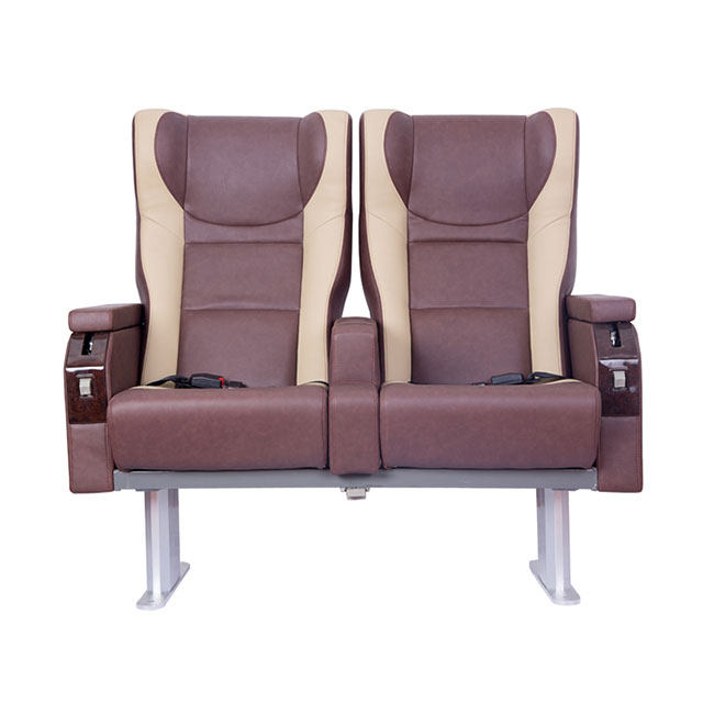
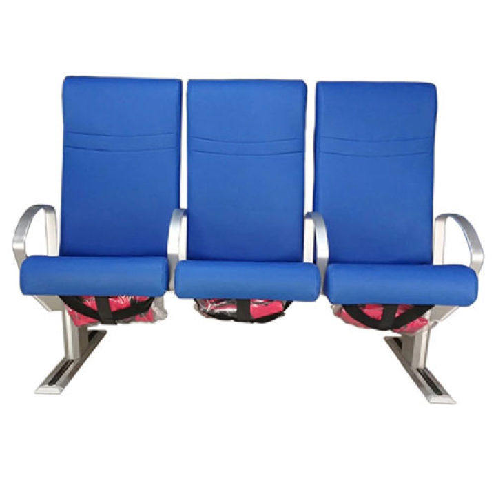
Comfort Amplified: Extended voyages across the open sea can exact a toll, necessitating the presence of supremely comfortable seating. Equipped with optimal support, cushioning, and ergonomic design, these seats provide a reprieve from fatigue, nurturing passenger well-being throughout the journey.
Stability and Safety: The unpredictable marine environment is rife with tumultuous waters and capricious conditions. Robustly constructed marine passenger seats serve as beacons of stability, mitigating the risk of accidents or falls. The inclusion of armrests and seat belts bolsters these safety measures, cocooning passengers in protective embrace.
Ingenious Space Efficiency: Within the confines of marine vessels, space is a prized commodity. Marine passenger seats are astutely designed to maximize space utilization, allowing for optimal seating arrangements that accommodate more passengers without compromising their well-being or comfort.
Durability and Endurance: The formidable marine setting subjects materials to an array of adversities—saltwater exposure, extreme temperatures, and ceaseless vibrations. Constructed from robust materials and fortified with specialized coatings, marine passenger seats emerge as stalwarts against the elements, promising enduring structural integrity.
Adherence to Stringent Regulations: The maritime domain operates under exacting safety regulations. Marine passenger seats are crafted to meet these rigorous criteria, encompassing attributes such as seat anchoring, fire resistance, impact resilience, and the capability for emergency egress. Complying with these standards ensures passenger safety in the face of adversity at sea.
Aesthetic Enhancement: Beyond functionality, marine passenger seats contribute to the ambiance and aesthetics of vessels. A myriad of styles and finishes cater to personalization, harmonizing seats with the vessel's interior design and branding.
Fostering Passenger Contentment: The nexus between well-designed, comfortable seating and heightened passenger satisfaction is undeniable. Enhanced passenger experiences lead to positive feedback, repeat business, and referrals—rendering the provision of comfortable and enjoyable travel experiences a cardinal goal for maritime transport companies.

Materials Nurturing Resilient Marine Passenger Seats
The construction of marine passenger seats is a symphony of materials curated for their resilience, corrosion resistance, and ability to brave the maritime crucible.
Marine-Grade Aluminum: Renowned for its lightweight disposition, impressive strength-to-weight ratio, and unparalleled corrosion resistance, marine-grade aluminum alloys are stalwart contenders in marine seat construction. These seats exemplify repairability, resilience against seawater, and a steadfast structural integrity.
Stainless Steel: Stainless steel stands as another exemplar material, exuding exceptional corrosion and rust resistance that align with the demands of the marine milieu. Durable, sturdy, and low-maintenance, stainless steel seats are a fitting choice for the marine environment.
Fiberglass: Fiberglass-reinforced polymers (FRP) find their way into marine passenger seat construction, offering resistance to corrosion, water, and UV light. Lightweight yet robust, fiberglass seats are marked by structural stability and can be sculpted into diverse shapes and designs for a personalized touch.
Specialized Plastics: Specialist plastics, including high-density polyethylene (HDPE) and acrylonitrile butadiene styrene (ABS), play a pivotal role in crafting marine seats. These plastics are impervious to water, solvents, and UV rays, embodying lightweight durability and simplified maintenance.
Maritime-Grade Upholstery Fabrics: The seating surfaces of marine passenger seats embrace maritime-grade upholstery textiles, meticulously tailored to thrive in coastal environments. These textiles display resistance to water, salt, fading, and mildew, coupled with UV resistance and rapid drying.
Cushioning with Foam: Upholstered comfort is augmented by high-density foam cushioning, offering passengers support during extended journeys while warding off moisture and mold growth.
Upholding the Splendor of Marine Passenger Seats
Maintaining the longevity, efficacy, and passenger well-being that marine passenger seats epitomize hinges on a judicious maintenance regimen.
Periodic Cleansing: Routinely cleanse seats to banish accumulated dirt, salt, or debris. Utilize mild detergent or soap solutions, coupled with gentle brushes or sponges, to clean seating surfaces. Caution against abrasive cleansers or harsh chemicals that could compromise seat materials.
Upholstery Reverence: Upholstered surfaces warrant specialized care. Regular vacuuming or brushing keeps dust and dirt at bay. Treat stains promptly with gentle cleaning products suited for marine-grade upholstery materials. Ensuring complete dryness prevents mold or mildew.
Scrutiny and Rectification: Regular scrutiny unveils wear, loose fittings, or damage. Cast a discerning eye on seat frames, fasteners, and anchoring systems for signs of rust or structural compromise. Swiftly replace worn-out or broken components, adhering to manufacturer guidelines or seeking expert counsel.
Lubrication: Seats featuring moving components—hinges or swivel mechanisms—demand regular lubrication with marine-grade lubricants. Adhere to manufacturer recommendations to stave off friction and wear.
Shielding from Sunlight: Sunlight's erosive effect warrants safeguarding. Protective covers or shadings shield seats from direct sunlight exposure when not in use.
Saltwater Rinse: Saltwater exposure necessitates thorough cleansing after each usage. Salt's corrosive potential mandates diligent rinsing to eliminate residue, followed by meticulous drying to avert moisture-related complications.
Embrace Manufacturer Guidance: Embrace manufacturer's maintenance directives. These guidelines offer insights into care instructions, recommended cleaning agents, and bespoke maintenance requisites tied to seat materials and design.
In Summary
The voyage aboard maritime vessels hinges on the bedrock of marine passenger seats that constructed to weather the marine maelstrom, proffer comfort, safety, and functionality. In traversing the significance of these seats, the materials that shape them, and the art of their maintenance, a profound appreciation is fostered for their indispensable role in modern maritime travel.
In numerous industries, the seamless treatment of continuous web materials, such as paper, film, textiles, and metal, hinges upon the indispensable presence of web guiding systems. These systems play a pivotal role in ensuring meticulous web alignment and tension management, a necessity for eradicating defects, reducing wastage, and bolstering overall production efficiency. The infusion of sensor technologies into modern web guiding machines has orchestrated a paradigm shift in the handling of web materials, ushering in real-time feedback and automated adjustments that revolutionize the process. In this article, we delve into the cornerstone sensor technologies employed within web guiding machines, elucidating their contributions in propelling precision and efficiency within the realm of web handling processes.
Pioneering Line Edge Sensors in Web Guiding Machinery
The bedrock of precision lies in the innovative deployment of line edge sensors within web guiding machines. At their core, line edge sensors operate on the principle of discerning alterations in light, infrared, or sound patterns as the web material traverses their field of vision. This process involves the emission of light, infrared radiation, or ultrasonic waves across the expanse of the web. A harmonious signal is registered by the sensor when the web is suitably aligned, signifying that it adheres to its designated trajectory.
In cases of deviation, the line edge sensor swiftly detects fluctuations within the signal pattern. This triggers the web guiding system to execute meticulous adjustments, thereby rectifying the lateral positioning of the web and steering it back towards the centerline or the intended alignment.
The Diverse Variants of Line Edge Sensors
Optical Line Edge Sensors: Optical sensors harness light-emitting diodes (LEDs) to project a light beam across the width of the web. A receiver stationed on the opposing side detects the light pattern, which remains uninterrupted when the web maintains its proper orientation. Displacements in the web's position lead to alterations in the received light pattern, facilitating the sensor's calculation of the web's lateral placement and furnishing corrective inputs.
Infrared Line Edge Sensors: Employing the same principle as optical sensors, infrared line edge sensors substitute visible light with infrared radiation. This substitution renders them more impervious to external lighting conditions, making them especially adept in environments characterized by subdued ambient light.

Ultrasonic Line Edge Sensors: By generating ultrasonic waves that interact with the web before returning to the sensor, ultrasonic line edge sensors can gauge the web's distance and position. This technology proves efficacious for guiding materials of varying thicknesses and surfaces that may bear imperfections.

Harnessing Capacitive Sensors in Web Guiding Systems
Capacitive sensors, an indispensable component of web guiding systems, rely on the detection of capacitance changes brought about by the proximity of web content. As the material's dielectric constant fluctuates, so does the capacitance, allowing the sensor to identify the web's presence and position. This technology finds its forte in guiding non-conductive or low-conductive materials.
Vital Role of Tension Sensors in Web Guiding Systems
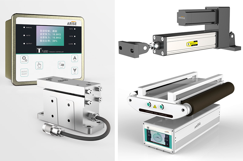
Tension sensors, veritable linchpins of web guide and tension control systems, wield the task of gauging and monitoring the tension forces acting upon moving web materials. Their role is pivotal in upholding continuous and precise tension throughout the web handling journey.
A Panoply of Tension Sensor Types
Load Cells: Hinging on the strain gauge principle, load cells undergo deformation when subjected to tension. Attached strain gauges discern this deformation and translate it into an electrical output proportional to the applied stress.
Dancer Roll Sensors: Employed in scenarios necessitating meticulous tension management, dancer roll sensors detect the position or angle of a freely-moving dancer roll—a roller responsive to fluctuations in web tension. This input aids in tension adjustments.
Ultrasonic Tension Sensors: Functioning through the measurement of ultrasonic waves' travel distance along the web, ultrasonic tension sensors deliver real-time tension feedback by constantly detecting changes induced by tension fluctuations.
Magnetic Tension Sensors: By detecting variations in the magnetic field's strength triggered by web stress, magnetic tension sensors cater to applications that demand non-contact sensing.
The Precision of Laser Sensors in Web Guiding Systems
Laser sensors emerge as exemplars of precision and accuracy within web guiding applications. Their modus operandi entails the detection of web position through laser beams, subsequently furnishing feedback for guiding adjustments. These sensors excel in high-speed processing and precision-intensive applications.
Summary
Sensor technologies have orchestrated a transformative epoch in the domain of web guiding machines, affording the luxury of real-time feedback and automated interventions that ensure impeccable alignment and tension control of web materials. Through the incorporation of these intelligent sensors, industries stand poised to elevate production efficiency, curtail wastage, and attain elevated levels of precision in the intricate realm of web handling processes.
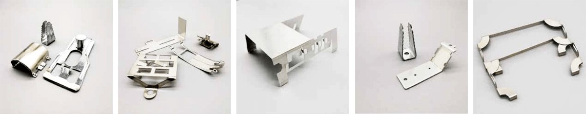
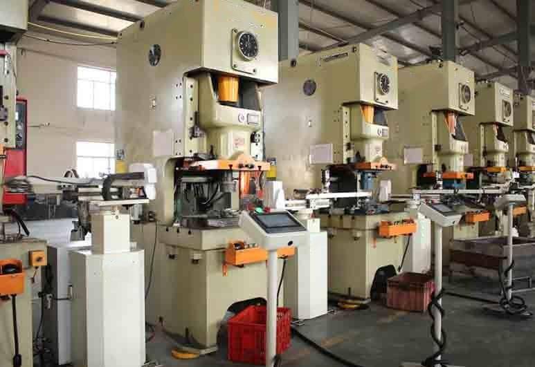
Metal stamping stands as a prevalent manufacturing process that involves employing a series of metal stamping dies to mold a metal sheet into intricate three-dimensional workpieces. It's vital to discern when to opt for metal stamping, understanding its advantages, and acknowledge its limitations.
Advantages of Metal Stamping:
Cost-Effectiveness and Automation:
Metal stamping boasts a distinctive advantage with its low-cost die utilization and high degree of automation. The manufacturing and maintenance expenses associated with metal stamping dies are often considerably lower compared to other prevalent processes. Additional costs like cleaning and electroplating are also minimized, contributing to overall cost-efficiency.
Precision in Dimensional Accuracy:
The inherent precision of stamping parts is ensured by the uniformity of the die's characteristics. The extended lifespan of the mold further guarantees stable stamping quality and exceptional interchangeability of components.
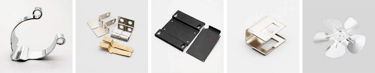
Versatility in Shape and Size:
Stamping exhibits unparalleled versatility in handling parts with an expansive range of sizes and intricate shapes. By virtue of the die manipulation, the process adeptly crafts items with thin walls, lightweights, robust rigidity, superior surface quality, and complex configurations that may otherwise pose challenges for alternative manufacturing techniques.
Economical Production:
Stamping often circumvents the need for blank heating and substantial material removal inherent in cutting processes. As a result, it consumes less material, yielding not only energy savings but also metal conservation.
High Efficiency:
Stamping's efficiency is remarkable. Regular presses can yield dozens of pieces per minute, while high-speed presses achieve even hundreds or thousands. Each stamping stroke generates a part, contributing to the process's remarkable efficacy. The stamping procedure aligns well with automation, leveraging sophisticated computer control systems for enhanced precision, accelerated production, and rapid turnaround, effectively curbing labor costs.
Disadvantages of Metal Stamping:
High Production Die Costs:
A significant drawback is the elevated cost of production dies. Unique to stamping, the need for various stamping processes to complete products necessitates bespoke dies. Constructing these custom metal stamping dies involves considerable investments, lengthy pre-production phases, and mandates precision-driven, experience-rich expertise from mold technicians.
Limitation for Single-Piece and Small Batch Production:
Stamping's reliance on specialized dies makes it optimal for mass production. It imposes limitations on single-piece and small batch manufacturing, aligning best with large-scale operations to truly leverage its benefits and derive optimum economic returns.
Mould Design Complexity:
Designing stamping mould demands a fusion of classical theory, imagination, and creativity. The process requires skilled die designers and manufacturers with an adept understanding of the intricate interplay between design and function.
Noise and Vibration:
Production often incurs significant noise and vibration, which may require additional attention to occupational health and environmental concerns.
Precision Challenges:
When stringent precision requirements are imposed, stamping may encounter limitations in meeting those demands. Intricate geometries and complex geometrical deviations might stretch the capabilities of the process.
Material Limitations:
While strides have been made in hot forming technology for high-strength and ultra-high-strength steel, cold forming of such materials remains a challenge. The growing demand for lightweight vehicle bodies and enhanced crash strength has spurred research into cold forming these advanced materials, but certain limitations persist.
Summary
Metal stamping presents a blend of advantages and disadvantages, making it a valuable tool within the manufacturing spectrum. By carefully evaluating the scope and requirements of a project, industry professionals can leverage the strengths of metal stamping while mitigating its inherent limitations.
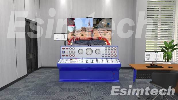
Within the oil and gas industry, the deployment of well intervention simulators has emerged as a pivotal strategy for replicating the intricacies of oil and gas well interventions. These advanced training tools serve as virtual laboratories, enabling practitioners to hone their skills, master techniques, and navigate complex procedures within a secure and controlled environment.

The Significance of Well Intervention Simulators in the Oil and Gas Industry
The integration of well intervention simulators holds profound importance in the oil and gas industry, primarily due to their provision of a secure and controlled training platform. These simulators facilitate practical exposure to intricate well intervention scenarios without subjecting participants to the inherent hazards and financial ramifications of real-world operations.
A key advantage of well intervention simulators lies in their potential to elevate industry safety standards. By affording a lifelike emulation of well intervention situations, personnel can acquire the necessary competencies to execute their tasks both competently and safely. This proactive approach diminishes the likelihood of accidents and incidents that can exert substantial tolls on both personnel and the environment.
Moreover, the application of well intervention simulators can substantially curtail downtime and expenditures typically associated with real-world operations. Armed with refined skills nurtured in a virtual realm, personnel can expedite their tasks and optimize efficiency when dealing with actual wells. This streamlined approach reduces the temporal and monetary investments associated with well intervention undertakings, ultimately yielding notable cost savings for industry stakeholders.
Furthermore, well intervention simulators offer the potential to enhance staff skill retention and knowledge assimilation. These simulators deliver a more engaging and memorable learning experience compared to traditional training methodologies. As a result, personnel are poised to enhance their competencies and overall performance, thereby fostering superior outcomes and heightened production levels.
Diverse Types of Well Intervention Simulators
Well intervention simulators manifest in various forms, each characterized by distinct advantages and constraints. The choice of simulator is contingent upon the specific needs and requisites of the operation. Noteworthy categories of well intervention simulators encompass:
Virtual Reality Simulators
Crafting immersive 3D environments through advanced software and hardware, these simulators replicate well intervention scenarios. Participants manipulate specialized tools and controls to interact within the virtual domain.
Hardware-Based Simulators
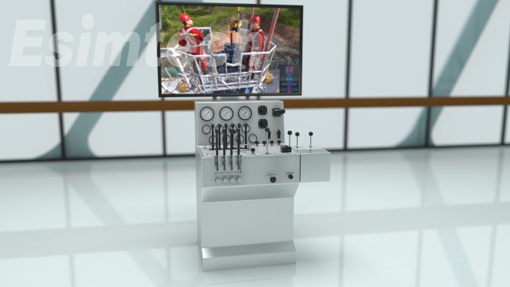
Utilizing authentic equipment and tools, hardware-based simulators simulate well intervention procedures. Hydraulic or pneumatic systems mimic the challenges and pressures encountered during such operations.
Critical Components of Well Intervention Simulators
The architecture of well intervention simulators incorporates various integral components, collaboratively delivering an authentic simulation experience. While specific elements may vary contingent on the simulator type and intended application, the following components are commonly featured:
Computer Hardware
Encompassing physical components like computers, displays, and input devices (e.g., keyboards, mice, joysticks), computer hardware constitutes the operational nucleus of the simulator.
Software
At the core of the simulator lies the software, which engenders the simulation environment, constructs scenarios, and interfaces with users. Analysis tools for post-simulation assessment and reporting may also be encompassed.
Visualization System
The visualization system transmutes simulation scenarios into 2D or 3D renderings. Monitors, projectors, and head-mounted displays for virtual reality simulations exemplify visualization components.
Input Devices
These devices empower users to manipulate the simulated environment. They encompass specialized tools, joysticks, and other tailored input mechanisms.
Hydraulic or Pneumatic Systems
In hardware-based simulators, these systems replicate the stress and pressure dynamics encountered during well intervention tasks.
Sensors and Instrumentation
Essential for monitoring and recording simulation data (e.g., forces, pressures), sensors and instrumentation play a crucial role in the simulator's functionality.
Data Acquisition and Storage
This facet collates and archives simulation data, facilitating post-simulation analysis and reporting.
Power Systems
Certain simulators, particularly those reliant on hydraulic or pneumatic power, necessitate dedicated power systems for optimal performance.
Challenges Confronting Well Intervention Simulators
Development and Maintenance Costs
Creating and sustaining effective simulators can be economically demanding, particularly when specialized hardware and software are requisite.
Limited Availability of Specialized Simulators
A dearth of comprehensive well intervention simulators on the market, especially tailored to specific needs, can pose challenges for businesses in identifying appropriate options.
Limited Access to Real-World Data for Simulation Models
The accuracy and efficacy of simulation models hinge on the caliber of data employed. Securing real-world data for these models can be intricate due to proprietary concerns.
Complexity of Well Intervention Scenarios
Accurately simulating multifaceted well intervention scenarios is intricate, as factors like wellbore geometry, formation attributes, and downhole equipment interplay to shape simulation accuracy.
Conclusion
The integration of well intervention simulators is important, facilitating secure and efficient personnel training, risk evaluation, and well intervention optimization. By furnishing a virtual realm that mirrors real-world circumstances, these simulators transcend conventional methodologies, augmenting industry competence and ensuring enhanced safety and efficacy in well intervention endeavors in the oil and gas industry.
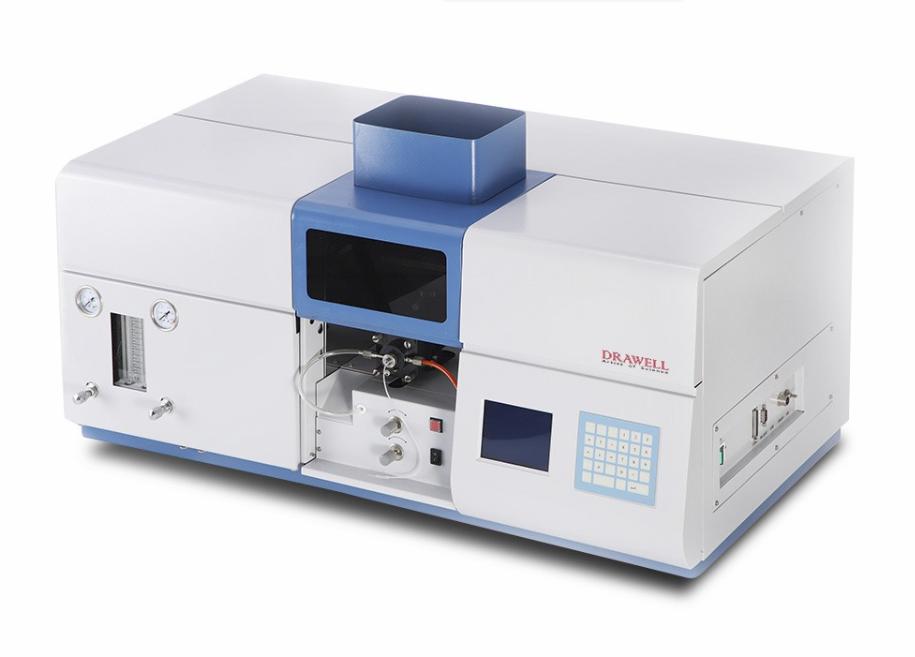
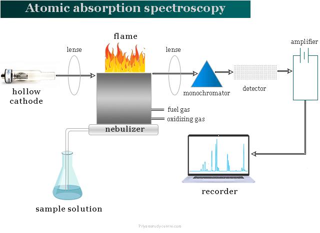
In the realm of analyzing test substances, the preliminary treatment of samples presents a complex challenge. This aspect is pivotal within the scope of analysis and detection efforts, constituting a significant facet for identifying the origins of detection inaccuracies. Consequently, this article aims to synthesize four fundamental sample pretreatment techniques employed in detection endeavors of Atomic Absorption Spectrophotometer (AAS) . Additionally, it delves into the foundational detection techniques for six categories of routine samples. These methodologies offer practicality and serve as valuable references for users of Atomic Absorption Spectrophotometers (AAS).
The Four Core Techniques for General Sample Pretreatment in AAS
Wet Digestion Method
For samples approximately ranging from 0.1000 to 0.5000g, prevalent mixed acids are utilized, with varying ratios as follows:
HNO3 : HClO3 = 5 : 1
HNO3 : H2SO4 = 5 : 1
HNO3 : HCl = 5 : 1
Pure HNO3
Note: Volatile (such as acetone, ether, ethanol, etc.) and flammable, explosive substances must be absent during the digestion process. While the wet digestion method is widely employed, its operational specifics will not be reiterated here.
Dry Ashing Method
Suitable for sample sizes typically ranging from 2.000 to 5.000g, this method involves careful treatment to prevent volatilization. The process entails placing the sample in a porcelain crucible, moistening it with a few drops of water, adding a small quantity of concentrated nitric acid, heating it gently to carbonize, and subsequently ashing it in a muffle furnace at around 550°C for 2 to 4 hours. Post-cooling, the residue is dissolved with additional acids plus HNO3 (1:1), which varies depending on the sample. The solution is then filtered, adjusted to volume, and readied in 10mL, 25mL, and 50mL portions for subsequent use.
High-Pressure Vessel Method (Utilizing Polytetrafluoroethylene Lid-Made Tanks)
When dealing with samples below 0.3000g, this method involves introducing 6mL of mixed acid and 1mL of HF (H2O2) to the sample. The lidded autoclave is then sealed, and heating is performed at 160°C for 5 hours. After cooling, the sample is filtered, adjusted to volume, and set aside for future use.
Microwave Digestion Method
In this approach, commonly employed mixed acids encompass:
HNO3 : HClO3
HNO3 : H2SO4
Pure HNO3
It is essential to select the appropriate acid for specific digestion depending on the sample. Readers are encouraged to make suitable choices as per their requirements.
Conventional AAS Analysis and Detection Approaches for Diverse Samples
Analysis of Pb, Cd, As, Mo, Cr, etc. (Graphite Furnace AAS Method)
Pb: Extract 1.0mL of the sample, dilute it to 10mL with 1% HNO3. Linear range: 0~20ng/mL, drying temperature: 80~100°C, ashing temperature: 200°C, atomization temperature: 1500°C.
Cd: Extract 1.0mL of the sample, dilute it to 10mL with deionized water. Linear range: 0.1~0.4ng/mL, drying temperature: 80~100°C, ashing temperature: 200°C, atomization temperature: 1800°C.
As: Extract 1.0mL of the sample, add 100μL of Ni (2mg/mL), dilute to 10mL with 1% HNO3. Linear range: 0~4ng/mL, drying temperature: 80~100°C, ashing temperature: 200°C, atomization temperature: 2200°C.
Mo: Prepare a 1.0mL sample diluted with 1% HNO3 to 10mL. Using Pd as a modifier, the linear range is 0-20ng/mL. Drying temperature: 80-100°C, ashing temperature: 1200°C, atomization temperature: 2600°C.
Cr: Sample 1mL, dilute to 100mL with deionized water, and proceed with appropriate testing. Linear range: 0~40ng/mL, drying temperature: 80~100°C, ashing temperature: 1000°C, atomization temperature: 2600°C.
Analysis and Testing of Se, K, Na, Ca, Mg, etc. in Plant Samples
Plant samples are subjected to washing, drying, fixation at 150°C for 10 minutes, subsequent drying at 70°C, and final comminution before analysis.
Se in forage grass: Extract 1mL of the sample, add 100μL of Ni(NO3)2 improver (3mg/mL), dilute to 10mL with 1% HNO3 and 0.1% Triton (1:1). Linear range: 0~20ng/mL, drying temperature: 80~100°C, ashing temperature: 1000°C, atomization temperature: 2400°C.
K and Na in plants: Weigh 0.2000g of the sample, add 10mL of mixed acid, extract in a constant-temperature water bath at 90°C, filter to 50mL volume, and proceed with suitable sampling and testing.
Ca and Mg in plants: Incinerate the sample at 550°C, dissolve with hydrochloric acid (1+1), adjust to 50mL volume (with 5% CsCl2 modifier 2 mL), and proceed with appropriate sampling and testing.
Beryllium Analysis in Mushrooms and Tea (Transverse Heating AAS Method)
Prepare the sample by washing, drying, fixation at 105°C, subsequent drying at 70°C, cooling, and crushing through a 60 mesh sieve.
Weigh 1.0000g of sample, add 15mL of HNO3, 1mL of H2SO4, digest at a low temperature, dilute to 25mL, and proceed with suitable sa
mpling for testing. Linear range for Be: 0~8ng/mL. Test conditions: drying temperature: 130°C, ashing temperature: 1500°C, atomization temperature: 2300°C.
Germanium Testing in Beverages (Utilizing Transversely Heated Flat Graphite Tubes)
Test outcomes indicate a linear range of 0~200ng/mL, using Ni(NO3)2 improver (50μg/mL) in a 1% HNO3 medium. Instrument conditions: drying temperature: 130°C, ashing temperature: 800°C, atomization temperature: 2000°C.
Calcium Detection in Steel Slag (Typically Employing Flame AAS Method)
For samples above 200 mesh, weigh 0.0500g into a 50mL PTFE crucible. Dissolve it with a water:nitric acid:hydrofluoric acid ratio of 5:8:6. Add sulfuric acid, heat, and adjust volume for analysis. To mitigate niobium interference, include
Triton-100 (20%), Vc (0.1 M/L), and 2% HNO3 as improvers.
Determination of Metal Elements in Blood Samples
Human blood encompasses diverse trace constituents, including heavy metal elements. Various detection methods can discern these components, with AAS being particularly effective. Specific digestion methods are elaborated in sections "2, 3), (3)." For instance:
Cu determination in serum (flame AAS method): Dilute 0.8mL of serum with 1% HNO3 to 10mL for testing.
As determination in serum (graphite furnace AAS method): Dilute with 1% HNO3 and utilize Ni(NO3)2 as a matrix modifier.
Cd determination in serum (graphite furnace AAS method): Process 2mL of serum with HNO3 and H2O2 for analysis.
Fe and Cu determination in albumin (flame AAS method): Utilize 1mL of the sample with mixed acid, adjust volume, and proceed with appropriate sampling.
Germanium determination in whole blood (graphite furnace AAS method): Dilute 1.0mL of venous blood, utilize a matrix modifier mixture, and perform analysis at defined temperatures.
This comprehensive overview highlights essential techniques for accurate analysis and detection of various samples by using atomic absorption spectrometry.