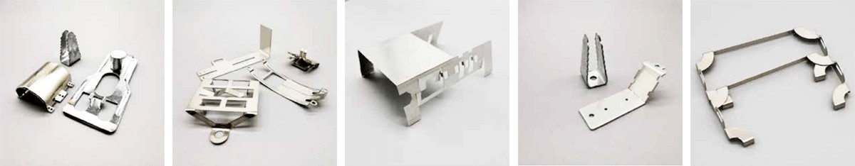
As society advances, the diversity of stamping products continues to expand, finding applications across various industries. To enhance efficiency, scrutinize work quality, and ensure product excellence, meticulous inspection of stamping parts becomes imperative. This article sheds light on prevalent inspection methods for stamping parts.
1. Flexible Gauze Mesh Grinding
Process:
Begin by cleansing the outer surface with clean gauze.
Employ flexible gauze mesh to systematically grind the entire surface of stamping parts along the longitudinal axis. This approach facilitates the identification of any pitting or indentations.2. Touch Test
Procedure:
Clean the outer surface with gauze.
Don touch gloves and gently touch the stamping parts along the longitudinal axis, assessing the presence of discernible burrs, indentations, scratches, rough edges, etc.
Note: This method relies on the inspector's experience and is a swift yet effective examination technique.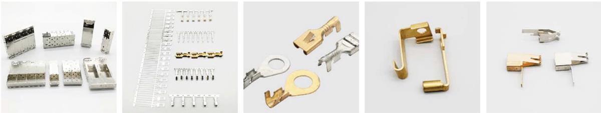
3. Visual Inspection
Steps:
Inspect the surface for rust, cracks, sand holes, slag inclusions, burrs, or blemishes.
Quality parts exhibit precision and a lustrous finish. Crucial components demand higher precision and stringent anti-rust packaging.
Check for secure bonding between parts. In multi-part assemblies, tight adhesion, gluing, or welding is essential to prevent looseness.
Note: Visual inspection primarily identifies surface irregularities and macro defects in stamping parts.
4. Grinding with Oil Stone
Protocol:
Clean the surface using gauze.
Employ an oilstone (20 × 20 × 100mm or more), and smaller oilstones for areas with curves or challenging access.
Note: Opt for a fine-grained oilstone; the grinding direction should align with the longitudinal axis. Horizontal grinding may complement certain spots.
5. Inspection with Special Tools
Method:
Place metal stamping parts into inspection tools and follow the tool manual to perform the inspection.
6. Oiling Inspection
Procedure:
Clean the surface using gauze.
Evenly apply oil across the stamping surface in the same direction using a clean brush.
Inspect the oiled parts under strong light.
Note: This technique effectively reveals minor pits, dents, ripples, etc. on the stamping parts.
7. Adopt Approximate Process Testing
In actual production, process tests akin to stamping operations—such as tensile and bulging tests—are often utilized to assess material stamping performance, ensuring high product quality and qualification rates.
Characteristics of Stamping Parts
Rapid Process Completion: Stamping accomplishes feeding, stamping, delivery, and waste disposal in minutes, yielding tens or hundreds of parts per minute.
Uniformity and Precision: Unified molds generate uniform products with minimal errors and high dimensional accuracy. Random sampling of such products exhibits a weighing error below 3%.
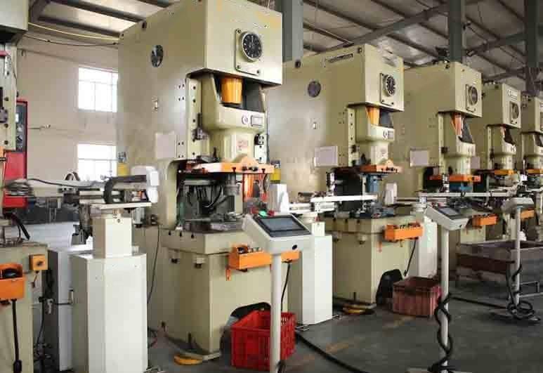
Stamping Equipment
Mechanical presses are predominantly used for stamping, along with hydraulic presses for thick plates. Combining conveying machinery, die libraries, and rapid die-changing devices, automated stamping lines boost productivity, supported by computer program control.
Impact of Stamping Molds
The precision and structure of stamping molds directly influence part formation and accuracy. Mold manufacturing cost and lifespan significantly impact part quality and cost. Mold design requires time, which extends preparation for new stamping parts.
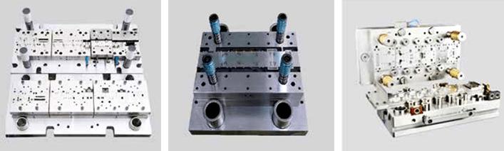
Trends in Stamping Mold Development
Standardized mold bases and guide pieces.
Innovation in simple molds (for small batches), composite molds, and multi-station progressive molds (for large-scale production).
Advancements in rapid mold change devices, aiming to apply advanced stamping technology to diverse production scales.
The goal is to streamline production preparation, making advanced stamping technology feasible for both mass production and small-batch, multi-variety production scenarios.
Given the intricate nature of snubbing operations and the need for skilled professionals to carry them out safely and effectively, the utilization of snubbing simulators is rapidly gaining significance within the oil and gas sector. Snubbing, a crucial well-servicing process involving the insertion of pressurized pipes into wells, demands specialized equipment and techniques to ensure pressure control and prevent hazardous blowouts.
Features and Advancements of Snubbing Simulators
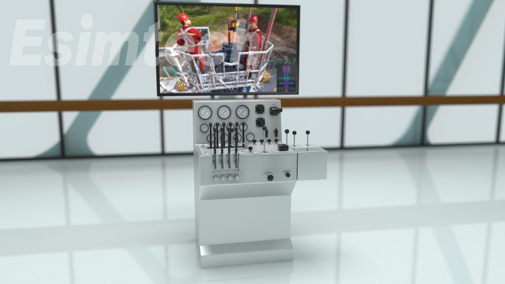
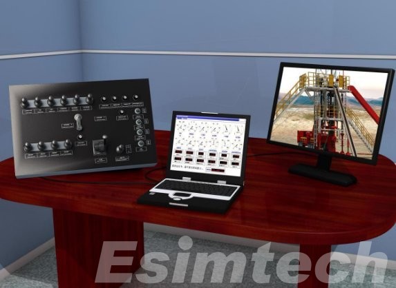
Two primary types, namely full-size snubbing simulators and portable snubbing simulators, are available, each designed to replicate diverse scenarios and challenges, enabling trainees to practice across a wide spectrum of settings.
Realistic Wellbore Replications
Snubbing simulators adeptly recreate an array of wellbore conditions, encompassing scenarios like high-pressure situations and stuck pipe occurrences. This realism facilitates experiential learning in a safe environment.
Tailored Scenario Simulations
Snubbing simulators are customizable to simulate various circumstances and challenges, providing trainees with exposure to an extensive range of settings.
Instant Feedback Mechanisms
Trainees receive real-time feedback on their performance from snubbing simulators, enabling them to identify areas needing improvement and make immediate adjustments.
Comprehensive Monitoring and Control Systems
Equipped with monitoring and control systems resembling hydraulic systems, pipe handling mechanisms, and control panels, snubbing simulators accurately replicate the functions of real snubbing machinery.
Diverse Control Modalities
Snubbing simulators offer various control options, including joystick and computer-based controls, allowing trainees to practice using familiar control interfaces.
Varied Training Modes
These simulators support a range of training modes, including individual and team-based approaches, accommodating diverse training needs.
Data Collection and Analysis
Snubbing simulators capture and analyze training data, empowering trainees to evaluate their performance and monitor progress over time.
Simulated Snubbing Operations
Snubbing simulators can simulate a multitude of snubbing operations, such as:
Pipe Insertion and Removal: Teaching safe and efficient methods for inserting and removing pipes from wellbores using snubbing equipment.
Pressure Control: Simulating varying wellbore pressures and imparting pressure regulation techniques during snubbing operations.
Tool Deployment and Retrieval: Training staff in deploying and retrieving downhole tools, like packers or pumps, during snubbing.
Wellbore Cleaning and Debris Removal: Replicating debris removal procedures and educating personnel on wellbore cleaning techniques.
Stuck Pipe Recovery: Instructing staff on proper procedures for extracting jammed pipes during snubbing.
Wellbore Remediation: Teaching wellbore rehabilitation strategies, including installing remedial equipment like liners or casing patches.
Specialized Snubbing Techniques: Training individuals in specialized snubbing methods, such as hydraulic snubbing that employs hydraulic power for tubular insertion or removal.
Technology Employed in Snubbing Simulators
Snubbing simulators comprise complex systems utilizing various technologies to replicate the functions of actual oil and gas snubbing units.
Hydraulic Systems: Simulating hydraulic functions of actual snubbing machines through pumps, hoses, and cylinders for movement control.
Pipe Handling Systems: Replicating real pipe handling systems using mechanisms like elevators, slides, and tongs.
Control Panels: Mimicking genuine snubbing unit control panels to monitor hydraulic and pipe handling systems.
Sensors and Actuators: Employed to measure and regulate hydraulic system movement and pressure, providing real-time performance feedback.
Computer Software: Operating hydraulic and pipe handling systems, customizing training scenarios, and gathering training data.
In Conclusion
Snubbing simulators significantly enhance training in the oil and gas industry, furnishing a secure and lifelike platform for personnel to practice a wide array of snubbing operations. These simulators enable organizations to ensure that their workforce is proficient in executing snubbing procedures, thereby enhancing safety, productivity, and efficiency within the industry.
Mastering the operational skills of the patient monitor, also known as a heart monitor, is an essential competence for every medical nurse. When it comes to utilizing ECG monitors, there are crucial operational aspects that cannot be overlooked.

Key Considerations for Operating Patient Monitors
1. Distinction Between 3-Lead and 5-Lead ECG Leads
Distinctions between 3-lead and 5-lead ECG leads are pivotal. The 3-lead ECG lead configuration captures ECGs from leads I, II, and III, while the 5-lead ECG lead setup captures ECGs from leads I, II, III, AVR, AFV, AVL, and V.
To streamline the connection process, an efficient color marking system is employed for quick and accurate placement of electrode pads. The color sequence for 3-lead ECG leads is red, yellow, green or white, black, and red; for 5-lead ECG leads, it's white, black, red, green, and brown.
It's important to note that electrodes of the same color have distinct placements in the two lead configurations. Utilizing English abbreviations such as RA, LA, RL, LL, and C is more dependable for electrode positioning compared to relying solely on color memorization.
2. Prioritizing Blood Oxygen Saturation Finger Cuffs
The preference for blood oxygen saturation finger cuffs stems from their speedier application compared to connecting ECG lead wires. These cuffs enable rapid monitoring of pulse rate and blood oxygen saturation, allowing medical staff to swiftly evaluate fundamental patient vital signs.
3. Limb Placement of Cuffs
Placing both blood oxygen saturation finger cuffs and automatic blood pressure monitor cuffs on the same limb is not recommended due to potential blood flow obstruction during blood pressure measurement. This interference can lead to inaccurate blood oxygen saturation readings.
4. Electrode Replacement for Continuous ECG Monitoring
In cases of continuous ECG monitoring, regular replacement of electrode pads is necessary. Prolonged adherence of electrode pads to the same area can lead to skin rashes and blisters. Frequent skin condition assessments are crucial to prevent skin breakdown.
5. Non-Invasive Blood Pressure Monitoring Considerations
a. Avoid measuring blood pressure on limbs with internal fistula, hemiplegic limbs, limbs affected by breast cancer resection, infusion sites, edema, and hematoma skin damage.
b. Routinely change the measurement site to prevent complications like purpura, ischemia, and nerve damage from cuff friction.
c. Pay attention to cuff and pressure value selection and adjustment for different age groups, avoiding pressure levels suitable for adults in pediatric cases and vice versa.
6. Respiration Monitoring
The monitor's respiration tracking relies on the thorax's impedance changes sensed by the ECG electrode pads. Optimal placement of the sensing electrodes (lower left and upper right) is crucial for accurate respiration waveforms, particularly for patients who predominantly breathe abdominally.
7. Alarm Range Settings
Alarm range settings should prioritize patient safety, minimize noise disruption, and avoid turning off alarms except when absolutely necessary during rescue operations. Alarm parameters should encompass heart rate variations within 30% above and below the patient's own heart rate, appropriate blood pressure thresholds, and oxygen saturation based on the patient's condition.
8. Troubleshooting Waveform Display Issues
If the monitor fails to display waveforms, the following steps are recommended:
a. Verify proper electrode pad placement and quality, along with correct lead wire connections.
b. Confirm accurate lead mode connections according to the ECG monitor's specifications.
c. If issues persist, check the contact quality of the "ECG signal line" on the parameter socket board, as well as potential faults in the ECG board, connecting lines, or main control board.

Patient Monitor Tips
Precise electrode pad application involves cleaning and preparing the skin, attaching ECG lead wires securely, and using appropriate cleaning solutions for optimal contact.
Patient and family education is vital to prevent unnecessary interference with the monitor and to ease any anxieties associated with its usage.
Regular maintenance includes electrode replacement, skin cleaning, and seeking professional assistance for substantial monitor abnormalities.
Proper grounding is crucial; ensure proper connection of the ground wire to the host's rear panel and a reliable common ground terminal.
By adhering to these operational guidelines, medical professionals can proficiently operate patient monitors, ensuring accurate vital sign monitoring and patient safety.
In the realm of advanced technologies, the web guide system stands as a sophisticated tool, meticulously overseeing the alignment and control of the paper web during the manufacturing process. Automatic web guiding control system plays a pivotal role in steering and governing the movement of the paper web as it navigates the manufacturing journey. Its impact is far-reaching, elevating precision, curbing waste, heightening productivity, and embellishing the quality of the final product by eradicating web inconsistencies and preserving impeccable alignment.
Delving into the subject of selecting the web guide system to augment accuracy and excellence in paper manufacturing, this article ventures into the mechanics, advantages, and principal applications of this system within the paper manufacturing landscape.
Unveiling the Mechanics of the Web Guide System in Paper Manufacturing
The Intricacies of Detection
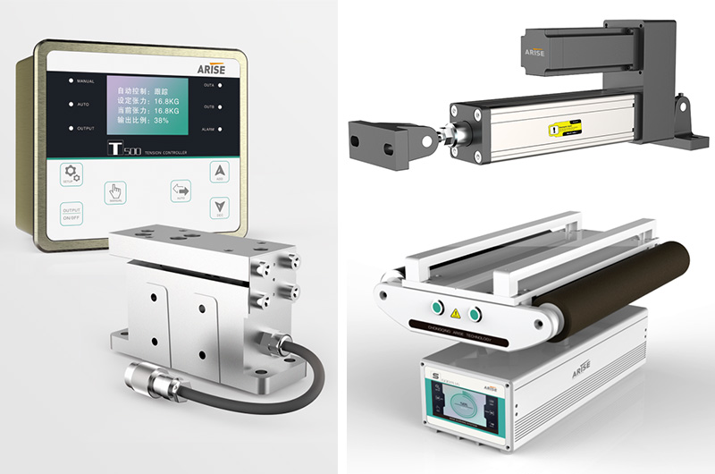
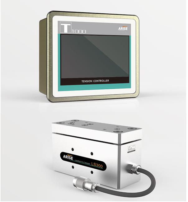
Central to the functionality of the web guide system is the vigilant web guide sensor, ceaselessly monitoring the real-time position of the paper web and detecting any deviations from its designated alignment. Subsequently, this data is relayed to the control system, setting the stage for corrective actions.
Analysis and Precision Calculation
Herein, the control system undertakes a profound analysis of the sensor-derived data, meticulously calculating the necessary adjustments required to bring the web back into harmonious alignment. This intricate calculation takes into account dynamic variables such as web speed, tension, and the intricate specifications of desired alignment.
Precise Adjustment Mechanisms
With calculations complete, the control system issues commands to the actuator, a dynamic component within the system. The actuator responds by engaging the web guide mechanism – a collection of rollers or guides, for instance – in orchestrated movements to rectify the web's deviation and return it to its intended trajectory.
Continual Supervision and Responsive Loop
Even as production proceeds, the web guide sensor maintains its steadfast vigilance, ensuring constant observation of the web's position. This perpetual feedback loop transmits real-time data to the control system, which, in turn, orchestrates the necessary modifications to keep the web exquisitely aligned throughout the entirety of the manufacturing journey.

The Merits of Embracing the Web Guide System in Paper Manufacturing
Precision Aligned Web: A Cornerstone Benefit
Foremost among the advantages bestowed by the web guide system is the fine-tuning of the paper web's alignment. This achievement ensures that the web remains unfailingly poised within its intended position during the multifaceted manufacturing process. By mitigating deviations and misalignments, this facet engenders a refined level of accuracy in printing, coating, and cutting processes, ultimately culminating in a spectrum of high-quality end products.
Amplified Productivity Beckons
The web guide system introduces a new era of enhanced production speeds without compromising on precision. By upholding optimal web alignment, it obviates the need for human interventions that were historically necessary to rectify misalignments. The consequent seamless functioning of the manufacturing process minimizes downtimes caused by web misalignments, which, in turn, charts an upward trajectory for productivity and overall output.
Slicing Waste at the Roots
Paper waste can cascade from the web's irregularities and misalignments. Mispositioned sections might be relegated to the wastebin, ushering in heightened material costs and an unwelcome environmental footprint. Enter the web guide system – the guardian of alignment – which abates waste by championing the sustained alignment of the entire paper web. Material waste is thereby curbed, and the manufacturing landscape inches closer to sustainability.
Quality Ascends the Throne
The pinnacle of the final product's quality rests upon precise web alignment. This tenet, upheld by the web guide system, vouchsafes consistent and exact results across the manufacturing trajectory, be it printing, coating, or cutting. The outcome: paper goods of impeccable quality, poised to exceed customer expectations and elevate the manufacturer's standing in the market.
Counting Coins: Savings Galore
For paper manufacturers, ushering in the web guide system can herald substantial cost reductions. Slashing manufacturing costs becomes a reality as waste reduction, amplified productivity, and diminished manual interventions collectively pave the way for economic gains. Furthermore, the system's astute management of material usage unfurls the banner of resource efficiency, culminating in sustainable cost cuts that reverberate over the long term.
Reducing Downtime, Elevating Efficiency
Web misalignments and fluctuations are notorious for triggering halts in production and precipitating downtime. The web guide system orchestrates a ceaseless ballet of vigilance and adjustment, rendering manual interventions and downtime largely obsolete. This synergy maintains the rhythm of continuous production and begets a realm of heightened operational efficiency.
A Tapestry of Adaptability and Versatility
The beauty of the web guide system lies in its adaptability. A chameleon in the realm of paper manufacturing, this system seamlessly accommodates a spectrum of paper types, sizes, and weights. It effortlessly melds into existing production lines, malleable enough to be tailored to the distinct manufacturing requisites of each entity. This dynamic capacity empowers manufacturers to navigate shifting paper demands with dexterity, rendering the production journey remarkably versatile and responsive.
User-Centric Harmony
The web guide control system, with its user-friendly interfaces and intuitive controls, caters to the operators' ease. Armed with such a system, operators can fluidly monitor and tweak system parameters as necessity dictates. This streamlined operation obviates steep learning curves for new users, fostering operator satisfaction and bolstering overall efficiency.
Charting the Vistas of Application: Web Guide System's Key Roles in Paper Manufacturing
Embarking on Seamless Alignment
At its core, the web guide system is synonymous with immaculate web alignment throughout the manufacturing odyssey. The system's vigilant oversight translates into lateral paper web movement regulation, meticulously positioning and aligning it along its intended path. This alignment is pivotal for a myriad of paper manufacturing phases, from printing and coating to cutting and converting.
Precision in Printing
In the realm of printing, the web guide system assumes a pivotal mantle, meticulously steering precise registration and alignment of the paper web. This orchestration ensures that the printing plates or cylinders are in harmonious accord with the web, ushering in sharply defined and impeccably aligned printed images. This attribute finds profound utility in the realm of high-quality printing, including periodicals, catalogs, and packaging materials.
Coating: A Uniform Canvas
Coating, a cornerstone technique in paper manufacturing, involves the application of a coating material to the paper web to augment attributes like smoothness, gloss, and printability. The web guide system steps in to champion this realm, guaranteeing unwavering alignment during the coating process. The outcome is uniformity and consistency in the application of coating, culminating in a coated paper of extraordinary quality, boasting evenly dispersed coating material.
Meticulous Cuts and Slits
The transformations from paper web to diverse sizes and forms necessitate slitting and cutting procedures. The web guide system plays a pivotal role in this domain, preserving the precision and linearity of cuts by impeccably maintaining web alignment during these operations. This contribution is of paramount importance in crafting paper rolls, sheets, or specific paper products marked by uniform dimensions and impeccable trims.
Tension's Tamed Grace
Tension control during papermaking finds a loyal ally in the web guide system. Its watchful eye ensures that the paper web is adorned with optimal tension levels, thwarting creases, wrinkles, and sagging. This guardianship over tension preserves the paper web's structural integrity, preventing quality setbacks in subsequent stages.
In a multitude of tasks, whether it's assembling furniture or electrical components, screws play an indispensable role in securing components together. Among them, the hexagon socket head cap screw stands out for its robust fixation capabilities and broad applications. This article dives into the intricacies of hexagon socket head cap screws, shedding light on their functions, advantages, and manufacturing requirements.

Understanding Hexagon Socket Head Cap Screws
The screw head boasts a distinct circular concave hexagonal shape, earning it the monikers of hex socket head screw, hexagon socket head bolt, or hexagon socket head cap screw. This unique design offers compelling advantages. Hexagon socket cap screws are typically crafted from materials like stainless steel, carbon steel, and alloy steel. Greater strength is achieved with higher performance-grade materials. These screws demand a special wrench for both installation and removal. Their primary function lies in mechanical fixation, with the hexagonal wrench playing a pivotal role. This wrench, featuring a 90-degree curved ruler, utilizes its extended side for increased torque during screwing, facilitating robust tightening. This design also mitigates the risk of thread slippage caused by misaligned screwdrivers.
Hexagon socket head cap screws find extensive use in machinery manufacturing due to their superior fixation capabilities. However, their utility extends beyond this realm, often finding application in hardware components, electrical products, and furniture assembly.
Manufacturing Demands for Hexagon Socket Head Cap Screws
Quality Raw Materials: Hexagon socket head cap screws' production necessitates the use of high-quality raw materials tailored to different customer applications. Clear classification of electroplating methods should be a priority.
Precise Specifications: Screw manufacturers must meticulously adhere to size and specification standards for hexagon socket screws to cater to diverse customer requirements.
Anti-Corrosion Measures for Hexagon Socket Head Cap Screws
Given the inherent corrosivity faced by metal materials, safeguarding hexagon socket head cap screws is vital. Corrosion-resistant methods ensure their durability and aesthetics. While these screws are employed to secure machinery, minimizing oil contamination is imperative. A dry environment enhances their longevity. Additionally, it's crucial to shield these screws from corrosive liquids to prevent air erosion.
Advantages of Hexagon Socket Head Cap Screws
Enhanced Load Bearing: With six force-bearing surfaces, hexagon socket screws offer superior load-bearing capabilities compared to slotted and cross screws, which have just two surfaces. Opt for hexagonal socket screws for high-stress applications.
Seamless Countersinking: The screw's entire nut is recessed within the workpiece, preserving surface flatness and aesthetics.
Ease of Installation: The inner hexagon design suits various assembly settings, especially those with space constraints. This ensures convenient assembly, maintenance, and debugging.
Security in Fixation: Hexagon socket bolts demand a specialized wrench for removal, making them resistant to casual disassembly.

In Conclusion
The prevalence of hexagon socket head cap screws across diverse industries is attributed to their potent fixation capabilities. This article elucidates the definition, functions, applications, and advantages, aiding in selecting appropriate hex socket head screws based on distinct application demands. In an ever-evolving landscape, understanding these screws empowers professionals to optimize their utility while ensuring steadfast and secure component assembly.