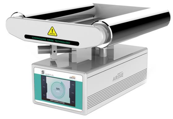
Web guiding systems have revolutionized the manufacturing industry, particularly in processes involving continuous web materials, by offering precise alignment and tension control. As production demands continue to rise, the choice of the right web guide system becomes increasingly critical. This article presents an extensive comparison of various web guiding systems, highlighting their operational principles, advantages, and ideal applications.
Line Edge Sensor-Based Web Guiding Systems
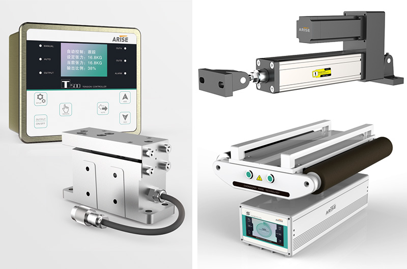
At the core of these web guide systems are web line edge sensors that detect changes in light, infrared, or sound patterns as web materials pass through their field of view. These sensors receive signals that reflect the alignment status of the web by emitting beams of light, infrared radiation, or ultrasonic waves across it. When the web deviates from its intended path, the sensor's signal pattern shifts, prompting the web guiding system to make precise adjustments, realigning the web to the centerline or ideal alignment. This real-time feedback loop ensures the web materials remain consistently aligned throughout the production process.
Benefits
Real-Time Alignment: Line edge sensors provide rapid feedback, facilitating quick adjustments and minimizing misalignment.
Non-Contact Detection: These sensors offer non-contact sensing, safeguarding fragile materials.
Versatility: Line edge sensors are compatible with a wide range of materials, making them suitable for various industries.
Ideal Applications
Printing: Ensuring accurate alignment of paper or labels during printing processes.
Packaging: Precise alignment of packaging materials for uniform packing quality.
Textiles: Maintaining fabric alignment for flawless weaving or printing.
Labeling: Accurate label alignment on products or packaging materials.
Converting: Ensuring precision in cutting, slitting, and perforation during manufacturing operations.
Tension Sensor-Based Web Guiding Systems
Web guiding systems equipped with tension sensors are designed to monitor and manage the tension forces applied to moving web materials. These sensors detect variations in tension and provide real-time feedback, enabling swift adjustments to maintain optimal tension.
Benefits
Uniform Tension: Tension sensor-based systems ensure uniform tension across the web material, preventing flaws like creases and stretching.
Versatility: Different sensor types cater to different material types and industrial processes.
Real-Time Feedback: Immediate adjustments guarantee proper tension, enhancing product quality.
Ideal Applications
Textile Weaving: Maintaining consistent tension for seamless fabric weaving.
Paper Manufacturing: Precise tension control during plastic film extrusion and lamination.
Film Production: Accurate tension control for plastic film extrusion and laminating.
Labeling and Packaging: Tension control during label application and packing material production.
Capacitive Sensor-Based Web Guiding Systems
Capacitive sensor-based web guiding systems rely on sensing changes in capacitance induced by the presence of web materials. These sensors excel in detecting the position and alignment of non-conductive or low-conductive materials, which can be challenging for other sensor types.
Benefits
Alignment for Non-Conductive Materials: Capacitive sensors are effective in aligning materials with low conductivity, a task that can be problematic for other sensor types.
Consistent Detection: These sensors offer reliable alignment detection irrespective of material characteristics.
Precision Alignment: High precision ensures superior product quality.
Ideal Applications
Plastic Film Processing: Ensuring precise alignment during plastic film extrusion and laminating.
Labeling and Packaging: Aligning labels on non-conductive packaging materials.
Paper Manufacturing: Accurate alignment of non-conductive paper during printing and processing.
Textile Production: Maintaining alignment of non-conductive materials during weaving and printing.
Summary
Choosing the right web guide system demands a comprehensive understanding of each technology's intricacies and its suitability for specific applications. Line edge sensor-based systems excel in swiftly aligning diverse materials, while capacitive systems thrive in aligning non-conductive materials. Tension sensor-based web guide systems are indispensable for ensuring consistency, while laser sensor-based systems offer unparalleled precision.

When selecting web guide systems, manufacturers must consider factors such as material properties, production environment, required precision, and budget constraints. Each system type presents its own set of advantages and limitations, enabling manufacturers to tailor their choice to their unique production needs. In a world where precision and efficiency are paramount, the ability to choose the appropriate web guiding system represents a crucial step in enhancing product quality, minimizing waste, and maintaining competitiveness in today's dynamic manufacturing landscape.
Bolts are an omnipresent component in various industries, playing a crucial role in connecting and fastening structures. However, have you ever wondered about the significance of those grade markings? In this article, we delve into the performance grades of bolts and screw threads.

Performance Grades of Bolts
Bolts used in steel structure connections come in various performance grades, numbering more than ten, including 3.6, 4.6, 4.8, 5.6, 6.8, 8.8, 9.8, 10.9, and 12.9. Bolts rated 8.8 and higher are crafted from low-carbon alloy steel or medium-carbon steel, treated through heat processes, and are commonly known as high-strength bolts. The rest are typically referred to as ordinary bolts. The grade markings on bolts consist of two figures, representing the nominal tensile strength value and the yield strength ratio of the bolt material.
For instance, a bolt with a performance grade of 4.6 signifies that the nominal tensile strength of the bolt material reaches 400 MPa, and the yield ratio is 0.6. In contrast, a high-strength bolt marked as 10.9 attains even greater strength after heat treatment, with a nominal tensile strength of 1000 MPa and a yield ratio of 0.9, achieving a nominal yield strength of 900 MPa.
It's important to note that the bolt performance grade is an internationally recognized standard. Bolts with the same performance grade exhibit uniform performance characteristics, regardless of their material or origin. Consequently, when designing structures, engineers rely on the performance grade as the key parameter.
In the realm of bolts, strength is typically expressed as "X.Y," where X * 100 equals the tensile strength, and X * 100 * (Y/10) equals the yield strength, given that yield strength/tensile strength equals Y/10, following standard identification regulations.
Performance Grades of Screw Threads
Screw threads are integral to countless applications, characterized by their uniform spiral profiles on solid surfaces, both internal and external. They can be classified into three primary categories based on their structural features and intended use.
Common Screw Thread: Featuring a triangular tooth profile, common threads are primarily used for connecting or fastening components. These threads come in coarse and fine variations, with fine threads offering enhanced connection strength.
Transmission Screw Thread: Transmission threads encompass trapezoidal, rectangular, sawtooth, and triangular tooth profiles, serving specific transmission purposes.
Sealing Screw Thread: Reserved for sealing connections, this category includes pipe threads, taper threads, and taper pipe threads.
The concept of thread fit refers to the degree of looseness or tightness between threaded components. Thread fit grades are defined by a combination of deviation and tolerance on both internal and external threads.
For instance, in the unified inch system, external threads have grades 1A, 2A, and 3A, while internal threads have grades 1B, 2B, and 3B. The higher the grade, the tighter the fit. Grade 1A and 1B offer loose tolerances, suitable for less critical applications, while grade 3A and 3B provide a tight fit suitable for safety-critical designs.
In metric threads, external threads are categorized as 4h, 6h, and 6g, while internal threads are categorized as 5H, 6H, and 7H, each with distinct applications based on their tolerance zones.

Thread Markings
Understanding thread markings is essential when dealing with fastener components:
Major Diameter/Tooth of Outer Diameter (d1): Represents the nominal diameter of the thread size.
Minor Diameter/Tooth Root Diameter (d2): Denotes the diameter where the thread root coincides.
Tooth Pitch (p): Refers to the axial distance between adjacent teeth on the meridian. In the imperial system, pitch is measured in teeth per inch, equivalent to 25.4mm.
Metric and Inch Self-Tapping Screws: These screws come in various specifications and pitches, allowing for precise applications.
In summary, understanding the grade markings of bolts, screws, and screw threads is vital, as different grades and markings indicate distinct applications and functions of bolts with different types in various industries and structures. Whether it's for high-stress steel connections or precise threading requirements, these markings provide essential information for engineers and manufacturers alike.
The oil and gas industry is a multifaceted and ever-evolving industry, heavily reliant on efficient and secure gathering and transportation operations. Traditionally, training within this sector demanded extensive on-the-job experience, often consuming valuable time, financial resources, and posing potential safety risks. Enter the Oil and Gas Gathering and Transportation Simulator, a cutting-edge solution harnessing the power of virtual reality (VR) and simulation to offer a realistic and immersive training experience for oil and gas professionals. In this article, we delve into the essence of the Oil and Gas Gathering and Transportation Simulator, exploring its key attributes and the benefits it brings to the industry.
Understanding the Oil and Gas Gathering and Transportation Simulator
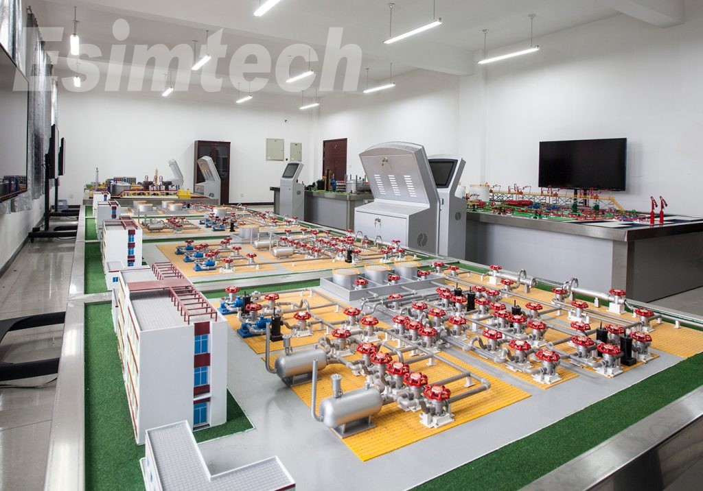
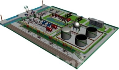
The Oil and Gas Gathering and Transportation Simulator represents a groundbreaking training tool that leverages virtual reality (VR) and simulation technologies to construct a virtual realm mirroring the intricacies and challenges encountered in actual gathering and transportation scenarios.
This state-of-the-art simulator equips trainees with VR headsets, immersing them in a simulated environment where they can interact with various gathering and transportation components and equipment. This virtual landscape accurately replicates pipelines, tanks, compressors, pumps, valves, and other vital industry infrastructure. Trainees gain the ability to monitor pipeline integrity, conduct equipment inspections, manage flow rates, and effectively respond to crisis situations.
Moreover, the simulator offers a wide array of tailored scenarios, replicating diverse operational conditions such as fluctuating weather patterns, equipment malfunctions, and maintenance demands. This controlled environment allows trainees to refine their skills and make informed decisions, free from the real-world consequences of any missteps.

Key Features and Advantages of the Oil and Gas Gathering and Transportation Simulator
1. Realistic Simulation
The simulator provides an astonishingly lifelike virtual environment, faithfully mirroring the complexities of oil and gas gathering and transportation processes. Trainees undergo a genuine representation of their responsibilities and the challenges posed by real-world scenarios, encompassing everything from infrastructure and equipment to ever-changing weather conditions.
2. Immersive Virtual Reality Experience
The simulator with virtual reality (VR) technology delivers an immersive experience to trainees through . Donning VR headsets, they fully engage with the virtual environment, becoming wholly absorbed in gathering and transportation operations. This heightened level of immersion significantly enhances training effectiveness, promoting deeper engagement and more fruitful learning outcomes.
3. Hands-On Training
The simulator allows students to actively interact with simulated pipelines, tanks, compressors, pumps, and other equipment, offering a hands-on approach to training. Trainees can gain practical experience in a controlled environment, engaging in tasks such as monitoring, inspection, and responding to emergencies. This hands-on training fosters skill development and boosts confidence in handling real-world challenges.
4. Safety Training and Risk Mitigation
Safety is paramount in gathering and transportation operations. The simulator serves as a platform for practicing safety protocols, emergency response procedures, and risk management techniques. Trainees learn to detect and efficiently manage potential hazards and incidents by simulating these scenarios, fostering a safety-conscious mindset and enhancing safety performance in the field.
5. Performance Tracking and Analytics
The simulator includes features for performance tracking and analytics, enabling trainees and organizations to measure and evaluate performance. Trainees receive feedback on their actions and decisions, helping them identify areas for improvement. Analytics empower organizations to assess overall training effectiveness, optimize programs, and make informed decisions regarding skill development and budget allocation.
6. Cost-Effectiveness
In contrast to traditional training methods, the simulator offers a cost-effective alternative. It reduces the need for physical resources, site preparation, and logistical arrangements, thus driving down associated costs. Trainees can acquire valuable expertise and competence in a virtual setting, reducing on-the-job training durations and operational disruptions.
7. Continuous Learning and Refresher Training
The simulator facilitates ongoing learning and refresher training for the oil and gas industry. As new technologies, procedures, and regulations emerge, trainees can return to the simulator to refresh their knowledge and stay abreast of industry developments. This adaptability ensures a continuous pool of expertise, ready to meet evolving industry demands.
In Conclusion
The Oil and Gas Gathering and Transportation Simulator represents a significant advancement in oil and gas industry training technology. This revolutionary solution, combining virtual reality and simulation, provides a secure, realistic, and cost-effective training environment. It empowers industry professionals with the skills and knowledge needed to excel in gathering and transportation operations, ultimately enhancing safety and efficiency in this dynamic sector.
Raman spectrometers are indispensable tools in laboratory testing. As a Raman spectrometer manufacturer, Drawell is here to address some of the most frequently asked questions about these instruments.

1. Laser Raman Spectroscopy vs. Infrared Spectroscopy
To grasp the difference between laser Raman spectroscopy and infrared spectroscopy, imagine their spectral shapes. Infrared spectra appear "concave," while Raman spectra are "convex." These two techniques complement each other in several ways:
Both are vibrational spectra, measuring the excitation or absorption of the ground state with the same energy range.
Raman is a differential spectrum. Infrared is like buying a Coke for $0.01 – straightforward. Raman, on the other hand, is like investing $1 and getting a Coke plus 90 cents back, but you still know the Coke's price.
They follow different selectivity rules. Infrared measures changes in molecular dipole moments, while Raman detects changes in molecular polarizability.
Infrared is known for its strong and easily measurable signal, while Raman typically has a weaker signal.They use different wavelength ranges. Infrared relies on mid-infrared light, which can't penetrate many optical materials. Raman, however, offers various wavelength options, from visible light to near-infrared.
Sample preparation for infrared can be complex and time-consuming, potentially damaging the sample. Raman spectroscopy doesn't face these challenges.
In most cases, Raman and infrared spectroscopy complement each other, with one being strong where the other is weak.2. Blue Shift and Red Shift
Blue shift and red shift describe shifts in wavelength or wave number:
Redshift means a wavelength moves toward longer wavelengths and lower frequencies, often seen in astronomical observations.
Blueshift refers to a shift toward shorter wavelengths and higher frequencies.
These shifts can also occur in molecular spectroscopy, affecting the position of absorption peaks in chromophores due to factors like molecular interactions and solvents.
3. Laser Light Sources in Raman Spectrometers
Raman spectrometers use various laser light sources:
Argon ion lasers
Semiconductors
Helium-neon lasers
Solid-state diode-pumped lasers
Near-infrared lasers (e.g., 785nm)
Neodymium-doped yttrium aluminum garnet (YAG) lasers (1064nm)
Dye lasers
The choice depends on your research object and the need to avoid interference, such as fluorescence.

4. Sample Pretreatment for Laser Raman Testing
Sample pretreatment in laser Raman testing is generally straightforward. Solids and liquids typically require no pretreatment, while gases can be more challenging, especially if they have low density. Polishing the sample surface or cleaning with solvents like alcohol or acetone is often sufficient.
5. Choosing the Excitation Wavelength
The excitation wavelength choice in Raman spectroscopy depends on whether the sample fluoresces under laser excitation. If fluorescence interferes, a different laser should be used. Shorter excitation wavelengths are preferred theoretically, but practical limitations, such as detector sensitivity, can impact the choice.
6. Fourier Transform Raman Spectroscopy vs. Laser Raman Spectroscopy
Fourier Transform Raman Spectroscopy uses a near-infrared laser (1064nm) for organic sample analysis with a weak signal.
Laser Raman Spectroscopy uses lasers of different wavelengths (200-800nm) for high-energy, high-sensitivity measurements.
Fourier Raman can reduce fluorescence interference.
It is generally more affordable.
Dispersion laser Raman is more popular among users.
In conclusion, these FAQs provide insights into Raman spectrometers, but there's more to explore. If you seek further information or wish to find the right Raman spectrometer for your needs, please don't hesitate to contact us. We'll guide you to the ideal product.
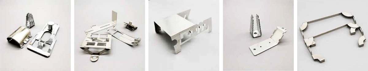
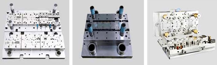
At its core, the stamping process is a metal fabrication technique founded upon the principles of plastic deformation. This method harnesses the prowess of stamping equipment and molds to exert controlled pressure on sheet metal, thereby inducing plastic deformation or separation. The ultimate goal is to sculpt these materials into parts with specific shapes, sizes, and performance attributes, collectively known as metal stamping parts.
The Impact on Automotive Manufacturing:
In the realm of automotive manufacturing, the stamping process stands as a pivotal player, particularly when it comes to crafting substantial body components. These encompass intricate shapes, expansive dimensions, and even spatially curved surfaces. To meet these demands, the art of stamping processing is harnessed. From truck cabs and front sheet metal components to car body panels and diverse bus frameworks, a significant portion of these elements arises from the meticulous practice of stamping.
The Distinct Traits of Stamping Process:
Efficiency and Minimal Material Consumption: Stamping is lauded for its remarkable efficiency in production and its judicious use of materials. With its inclination towards large-scale production, mechanization, and automation are readily achievable, resulting in heightened productivity. Additionally, the process is adept at minimizing waste and optimizing material usage, even accounting for intricate geometries.
Accessibility and Convenience: The beauty of the stamping process lies in its ease of operation, requiring minimal skill levels from operators. This convenience extends without compromising dimensional precision.
Dimensional Accuracy: Stamping yields parts with impressive dimensional accuracy, often obviating the need for further mechanical processing.
Interchangeability: Stamping parts boast excellent interchangeability. This virtue stems from the stability of stamping processes, ensuring that a batch of parts can be readily interchanged without compromising assembly or product performance.
Surface Quality: Given that stamping employs sheet materials, the resultant parts showcase superior surface quality. This characteristic not only facilitates subsequent surface treatments like electroplating and spray painting but also elevates the overall product aesthetics.
Strengthening and Lightweighting: Stamping bestows parts with superior strength, stiffness, and reduced weight, a triumvirate that holds immense value across industries.
Cost-Efficiency: The mass production of stamped parts with dies incurs relatively low costs, presenting an economical solution.
Complexity Capabilities: Stamping can craft intricate shapes, often deemed challenging for other metal processing methods.

Key Stages in the Stamping Process:
Stamping frequently amalgamates several processes in its execution. The primary processes include blanking, bending, shearing, stretching, bulging, spinning, and shaping.
Blanking: This foundational step employs a die to separate materials, generating flat parts or preparing blanks for subsequent processes.
Bending: A plastic forming technique, bending manipulates sheet metal, pipe fittings, and profiles to achieve specific angles, curvatures, and shapes.
Deep Drawing: Also known as drawing or calendering, deep drawing employs a die to transform flat blanks into open hollow parts.
Stretch Forming: Tension is exerted on sheet metal through a tensile die to achieve uneven tensile stress and strain, expanding the sheet metal until it bonds with the die surface.
Spinning: Involving metal rotation, spinning creates hollow rotary parts by manipulating the blank's interaction with a spinning die or head.
Shaping: This involves secondary trimming to refine abrasive tool shapes, commonly used for pressure planes and spring feet.
Bulging: Bulging employs a die to stretch thin sheet metal, enhancing surface area and forming open hollow parts.
Flanging: By bending the edge of thin sheet billets, flanging strengthens parts, fosters connections, and improves stiffness.
Shrinkage: This process reduces the diameter of stretched hollow parts or tube blanks without flanges, enhancing the overall form.
In Summary:
The stamping process stands as a testament to the marriage of innovation and craftsmanship in metal transformation. It has carved a niche in various industries, with its intricate procedures and intricate techniques, yielding parts that fulfill precise requirements. Its efficiency, adaptability, and ability to shape complexity make it an indispensable tool, guiding the creation of components that power the modern world.