Diesel engines are renowned for their efficiency and durability, finding applications in a wide array of machinery, from automobiles to heavy industrial equipment. Whether you're a seasoned technician or an eager enthusiast, understanding the intricate process of assembling and disassembling a diesel engine is paramount for maintenance and repair. In this article, we present a comprehensive step-by-step guide that takes you through the animation of intricate procedure for both diesel engine assembly and disassembly.
Step-by-Step Animation of Diesel Engine Disassembly
Engine disassembly is a pivotal phase in the maintenance, repair, or reconstruction of a diesel engine. Our step-by-step animation provides a clear and detailed method for dismantling various engine components:
Step 1: External Component Removal
The animation initiates with the removal of external components such as the air filter, fuel lines, and exhaust system. These parts are systematically disconnected and detached from the engine, creating unobstructed access to the internal components.
Step 2: Cylinder Head Removal
Following the external component removal, the animation proceeds to demonstrate the meticulous removal of the cylinder head. This intricate process involves the careful disconnection of the intake and exhaust manifolds, the valve train components, and the head bolts. Once these steps are completed, the cylinder head can be gently lifted off the engine block.
Step 3: Piston and Connecting Rod Removal
To access the pistons and connecting rods, the animation expertly guides you through each step of the removal process. This includes the removal of piston rings, the disconnection of connecting rod caps, and the safe extraction of the piston and connecting rod assemblies from the engine block.
Step 4: Crankshaft and Main Bearing Removal
The animation then focuses on the crankshaft, a critical component responsible for translating the piston's up-and-down motion into a rotating motion. Here, you'll witness the removal of the main bearing caps, allowing for the careful extraction of the crankshaft from the engine block.
Step 5: Camshaft and Timing Gear Removal
In the final phase of engine disassembly, the animation tackles the removal of the camshaft and timing gears. These vital components play a pivotal role in regulating the engine's valve openings and closings and ensuring precise timing. The animation meticulously demonstrates the separation of the camshaft, removal of the timing gears, and disengagement of the timing chain or belt.
By following these step-by-step instructions, technicians and enthusiasts alike can proficiently disassemble an engine, inspect its internal components, and perform necessary repairs or replacements.

Step-by-Step Animation of Diesel Engine Assembly
Engine assembly is a precise and intricate procedure that involves methodically piecing together various components to create a fully operational engine. Our animation walks you through this assembly process step by step:
Step 1: Camshaft and Timing Gear Installation
The animation commences with the installation of the camshaft, timing gears, and timing chain or belt. Precise alignment and synchronization are crucial for optimal engine performance. You'll witness the correct placement and installation of the camshaft and timing gear assembly.
Step 2: Crankshaft and Main Bearing InstallationNext, the animation guides you through the installation of the crankshaft and main bearings. The crankshaft is meticulously positioned and aligned within the engine block, with the main bearing caps tightened in the proper sequence and to the recommended torque specification. This step ensures smooth rotation of the crankshaft and proper support.
Step 3: Piston and Connecting Rod Installation
The animation then focuses on the installation of pistons and connecting rods. This involves precise positioning of piston rings on the pistons and secure attachment of connecting rods to the crankshaft. You'll witness how these components should be oriented and assembled to ensure efficient combustion and power delivery.
Step 4: Cylinder Head Installation
The animation illustrates the installation of the cylinder head in this step. Proper positioning of the cylinder head onto the engine block, along with the installation of new head gaskets, is crucial to create a tight seal. The animation emphasizes the correct torquing sequence and values for the head bolts to achieve the necessary clamping force.
Step 5: Reassembly of External Components
In the final phase of engine assembly, the animation demonstrates the reconnection and secure attachment of external components, including the air filter, fuel lines, and exhaust system. These components are essential for the engine's proper functioning and optimal performance.
In summary, understanding the intricate processes is paramount for effective maintenance and repair of diesel engines. This article's step-by-step animation guide of diesel engine assembly and disassembly provides a visually informative explanation of these complex procedures, empowering technicians and enthusiasts to navigate the intricacies involved. By following these methods, you can ensure the reliability and longevity of your diesel engine.
Gas chromatography, a powerful analytical technique, employs gas as a mobile phase within a chromatographic column. This core component of gas chromatography significantly influences the overall performance of the technique. Chromatographic columns come in two main types: packed columns and capillary columns.
Packed columns are filled with solid adsorbents or carriers containing fixed liquids. They are versatile, capable of separating compounds with high boiling points like nitrogen, oxygen, hydrogen, and argon. On the other hand, capillary columns offer high separation efficiency by coating the inner wall with a stationary phase liquid. This phase can be solid or liquid, each with distinct adsorption capacities for various components. Examples of weak adsorbents include sucrose, starch, inulin, talc, and potassium carbonate.
Gas chromatography boasts several outstanding advantages:
High Separation Efficiency: It can effectively separate complex mixtures of compounds with closely matched physical and chemical properties. This enables both qualitative and quantitative analyses, sometimes resolving tens or even hundreds of components simultaneously in a single analysis.
High Sensitivity: Gas chromatography can detect impurities at the ppm or even ppb level. Only minute gas or liquid samples, often less than 1 mL, are required for analysis.
Rapid Analysis: With the aid of computers, precise results can be obtained in seconds, making it a swift analytical method.
Wide Range of Applications: Gas chromatography is versatile, capable of analyzing gaseous, volatile liquid, and solid samples. It finds extensive use in organic analysis, covering approximately 20% of organic compounds, and can even analyze some inorganic substances following appropriate transformations.
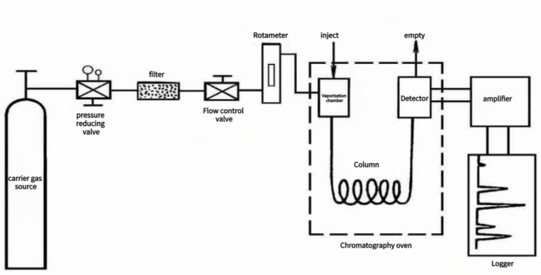
The General Procedure for Gas Chromatography:
The sequence of peak times serves as the basis for qualitative analysis, while peak area or peak height is used for quantitative analysis.
Three Components of Industrial Gas Chromatography:
Industrial gas chromatography, compared to its laboratory counterpart, incorporates a sampling system, utilizes column-cutting technology, and employs complete automation for program control and information processing.
1. Sampling System:
The sampling system handles sample collection and pretreatment, serving as the interface between the production process and industrial gas chromatography. Initial sample pretreatment steps, such as decompression, water removal, and dust removal, occur external to the chromatography system.
Internally, the gas chromatography system features functionalities such as pressure regulation, flow path switching, flow monitoring, atmospheric balance, and calibration with standard gas or liquid. Design considerations encompass corrosion resistance of system components, leak prevention, explosion protection, reduction of transfer lag time, and control of contamination from evacuation.
2. Carrier Gas Flow System:
The carrier gas flow system comprises a source of carrier gas, purifiers, pressure and flow stabilization, and adjustment devices. Typically, high-pressure gas stored in cylinders serves as the carrier gas source, with a pressure-reducing valve reducing it to 0.1-0.5 MPa. High purity and stability are prerequisites for the carrier gas, necessitating the use of materials like silica gel, molecular sieve, and activated carbon to adsorb moisture and hydrocarbon compounds.
Carrier gases such as hydrogen, nitrogen, and argon may be employed. Maintaining constant gas flow with minimal variation (<1%) is crucial, necessitating the inclusion of flow meters, regulating valves, and pressure-stabilizing valves in the gas path.
3. Sampling Device:
Sampling involves the quantitative introduction of a gas, liquid, or transformed solid sample into the chromatographic column for separation. Consistency in injection quantity, injection duration, and sample vaporization rate significantly impacts the repeatability and accuracy of quantitative results.
(1). Gasification Chamber:
The gasification chamber features a metal block exterior with a controllable operating temperature ranging from 50-500°C. Temperatures exceeding 250°C utilize inner glass tube structures to prevent unwanted catalytic effects. The gasification chamber's primary function is to ensure instantaneous vaporization of liquid samples. It requires preheating of the carrier gas before entry, while the silicone rubber pad should remain cool to prevent unintended chemical reactions.
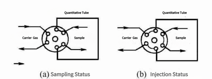
(2). Injection Valve:
Sampling valves must exhibit excellent airtightness, minimal dead volume, reliability, durability, and rapid switching times. In specific applications, resistance to corrosion and operation within defined temperature ranges may also be necessary.
Navigating the vast and often perilous expanses of the world's oceans has been a challenge throughout history. The maritime sector places a high priority on the safety of ships, crews, and cargo, with navigation lights being a crucial element in ensuring this safety. Marine navigation lights play a vital role in avoiding collisions, guiding vessels through congested waterways, and maintaining order on the high seas. In this article, we will explore how navigation lights contribute to enhancing maritime safety.

Understanding Navigation Lights
Navigation lights, also referred to as running lights, are specialized lighting systems installed on all types of vessels, from small pleasure crafts to massive cargo ships and oil tankers. These lights serve two primary functions:
Collision Avoidance: Navigation lights enable mariners to assess the direction, size, and type of approaching vessels. This information is essential for preventing collisions, allowing ships to take evasive action when necessary. Different combinations of lights indicate a vessel's condition and direction of movement.
Position Indication: These lights help vessels determine their relative position in relation to other ships. By observing nearby vessels' lights, mariners can ascertain whether they are on a collision course or safely passing each other.
Common Types of Navigation Lights
The International Maritime Organization (IMO) has established the International Regulations for Preventing Collisions at Sea (COLREGs), which mandate the use of navigation lights and define their configurations. Here are some commonly used types:
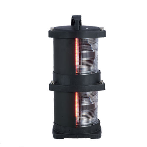
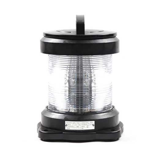
Masthead Light: A white light located at the forward end of a vessel, typically at the mast's highest point. It is visible from the front and sides and indicates the vessel's presence and direction.
Port (Red) and Starboard (Green) Lights: Colored lights situated on the vessel's left (port) and right (starboard) sides, respectively. These lights are critical for determining a ship's course.
Stern Light: A white light at the vessel's stern (rear), visible from behind and within a 135-degree arc on either side. It helps other vessels determine a ship's direction and relative position.
Towing Lights: Additional lights displayed on tugboats and vessels towing objects such as barges. These lights indicate the towing configuration and length.
Special Lights: Certain types of vessels, such as pilot boats, fishing vessels, and those restricted in their maneuverability, display unique lights to convey their status and intentions.
Strategies for Enhancing Maritime Safety with Navigation Lights
Navigation lights are a critical component of maritime safety, and it is imperative that all seafarers understand and utilize them correctly. Here are various strategie aimed at enhancing safety through navigation lights:
Adherence to COLREGs: Compliance with the International Regulations for Preventing Collisions at Sea (COLREGs) forms the foundation of navigation light safety. These regulations standardize navigation light arrangements, ensuring consistency in conveying information.
Proper Use and Maintenance: Regular inspections and maintenance procedures are essential to ensure that navigation lights are properly fitted, well-maintained, and in good working condition. This prevents equipment failures that could compromise safety.
Clear Visibility: Visibility is crucial for navigation lights to function effectively. Strategies for improving visibility include using clean and undamaged light fixtures, ensuring lights are not obstructed by cargo or equipment, and replacing worn or faded lenses.
LED Technology: Modern vessels are increasingly adopting LED navigation lights due to their energy efficiency, longer lifespan, and brighter illumination. LED lights offer improved visibility and are less prone to malfunction than traditional incandescent lights.
Backup and Redundancy: Having backup navigation lights and power sources onboard is a safety measure. These backups ensure that vessels can continue to display required lights in case of primary light failure or power outage.
Training and Awareness: Crew members should be well-versed in the use and interpretation of navigation lights. Raising awareness of the importance of navigation lights and their role in collision avoidance ensures compliance and understanding.
Automated Light Control Systems: Some ships are equipped with automatic light control systems that adjust the intensity and angle of navigation lights based on factors such as visibility conditions and vessel speed. These systems improve visibility and conserve energy.
Advanced AIS Technology: The integration of Automatic Identification System (AIS) technology with navigation lights provides real-time vessel identity, position, and course information to other vessels equipped with AIS receivers.
Enhanced Light Synchronization: Coordinating navigation light patterns with traffic movement can improve safety in congested rivers and ports, preventing confusion by ensuring nearby vessels have similar lighting settings.
Dynamic Positioning Systems: Modern vessels equipped with dynamic positioning systems can automatically control their location and direction. This helps ensure that navigation lights are always pointing in the right direction, enhancing visibility.
Incorporating LED Light Bars: LED navigation lights are commonly used on modern warships due to their energy efficiency, extended lifespan, and improved illumination, enhancing safety.
Integration with Bridge Systems: Modern bridge systems often integrate navigation light control, AIS data, and radar data on a single display. This integration enhances situational awareness and simplifies monitoring of nearby vessels.
Continuous Assessment and Improvement: Maritime operators should regularly evaluate their vessels' navigation light systems and safety practices. Staying updated with advancements in navigation light technology and regulations is essential, and equipment should be updated as needed.
Conclusion
Navigation lights are a vital component of maritime safety, enabling vessels to communicate their presence, status, and intentions to one another. By adhering to international regulations governing navigation lights, mariners can navigate the world's waterways with confidence, reduce the risk of collisions, and safeguard the safety of their crews, cargo, and the marine environment.
In high-speed web processing applications like printing, coating, laminating, and converting, maintaining precise tension control is paramount. Tension, in this context, refers to the force applied to a continuous web of material as it undergoes various manufacturing phases. This article delves into the importance of tension control, the challenges it presents, and the methods and technologies utilized to achieve it in high-speed web processing applications.

Why Tension Control Matters in High-Speed Web Processing
Tension control in high-speed online processing is not just a technical detail; it's a critical factor impacting product quality, resource efficiency, energy conservation, and overall operational effectiveness.
Ensuring Product Quality
Tension control plays a pivotal role in maintaining product quality. Consistent tension levels ensure uniform treatment of the web material, preventing defects like misaligned prints, distortion, smearing, or uneven coating distribution.
Reducing Waste
Precise tension control directly affects material utilization and waste reduction. High-speed processing often involves expensive materials, making it vital to prevent material breakdown due to over-tensioning or issues like wrinkling, misalignment, or tearing due to under-tensioning.
Enhancing Energy Efficiency
Proper tension control optimizes energy usage in high-speed web processing equipment. Over-tensioning can strain motors and drives, leading to increased energy consumption and maintenance costs. Maintaining constant tension contributes to cost savings and sustainability.
Boosting Process Efficiency
High-speed web processing requires synchronization among various components. Tension control acts as the linchpin, ensuring these components work efficiently together, reducing downtime, and enhancing overall process efficiency.
Reducing Defective Products
Tension control not only enhances product quality but also helps avoid the production of defective items, preventing financial losses and safeguarding a company's reputation.
Challenges of Tension Control in High-Speed Web Processing
Tension control in high-speed web processing faces numerous challenges due to the dynamic nature of these operations. Overcoming these obstacles is essential to maintaining product quality, reducing waste, and ensuring effective operation.
Variable Material Properties
Web materials exhibit variations in thickness, elasticity, and surface qualities, impacting tension control and requiring constant adjustments.
Speed Variations
High-speed processing involves rapid changes in web speed, which can introduce sudden tension fluctuations that must be managed for consistent product quality.
Web Accumulation and Splicing
Operations like web accumulation and splicing require precise tension control to prevent material and equipment damage during transitions.
Web Width Changes
Altering the width of the web can lead to tension fluctuations, necessitating real-time tension adjustments.
Web Flutter and Vibration
Dynamic forces like web flutter and vibration can be challenging to combat, requiring advanced control systems and responsive equipment.
Friction and Slip
Inconsistent friction and slip between the web and equipment components can affect tension control.
Complex Web Paths
Maintaining continuous tension in complex web paths with multiple rollers, guides, and direction changes can be difficult.
Load Variations
Variations in the amount of web material on a roll can impact tension and require adjustments.
Material Stretch and Shrinkage
Certain materials may stretch or shrink under tension, necessitating correction for precise control.
Temperature and Humidity Changes
Temperature and humidity variations can impact web material properties and cause tension differences.
Safety Considerations
Implementing safety mechanisms is essential to prevent over-tensioning, and safeguarding equipment and personnel.

Key Methods for Tension Control
Various methods and technologies are employed to achieve precise tension control in high-speed web processing applications:
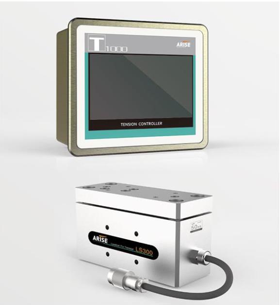
Dancer Systems
Load Cells
Pneumatic Brakes and Clutches
Closed-Loop Tension Control
Tension Control Software
Safety Mechanisms
The choice of tension control method depends on the specific requirements and challenges of the web processing application. In many cases, a combination of these strategies may be employed to achieve the necessary level of precision and responsiveness.
Conclusion
Tension control is indispensable in high-speed web processing applications, ensuring product quality, waste reduction, and process efficiency. Manufacturers can achieve precise and reliable tension control by integrating appropriate mechanical components, sensors, and control systems. As technology advances, the future of web tension control may bring even more sophisticated systems and automation, enhancing the potential of high-speed web processing across various industries, from printing to packaging and beyond.
In the realm of fastener surface treatment processes, several methods, including electroplating, electrophoresis, painting, oxidation blackening, and phosphating, are commonly employed. This article will focus on surface phosphating treatment, shedding light on its purpose, key factors influencing its effectiveness, and the advantages it offers.
What is Surface Phosphating Treatment?
Surface phosphating treatment is a chemical and electrochemical process that generates a phosphate chemical conversion film on metal surfaces. This film is referred to as a phosphating film and is primarily used on iron and steel surfaces, although it can also be applied to non-ferrous metals like aluminum and zinc.

Purposes of Surface Phosphating Treatment:
Enhancing Paint Adhesion and Corrosion Resistance: Phosphating treatment acts as a primer before painting, improving the adhesion and corrosion resistance of the paint layer. The porous nature of the phosphating film allows paint to penetrate into its structure, creating a strong bond with the metal surface.
Protecting Base Metal: It provides a protective layer on the base metal, reducing susceptibility to corrosion. The phosphating film serves as a non-metallic, non-conductive isolation layer, preventing the formation of micro-batteries on the metal's surface and effectively safeguarding the underlying metal from corrosion.
Anti-Friction Lubrication: Surface phosphating treatment can function as a lubricant in metal cold working processes, reducing friction and wear.
Creating a Clean Surface: Phosphating film only forms on clean, oil-free, and rust-free metal surfaces. Consequently, metal workpieces subjected to phosphating treatment exhibit a clean, grease-free, and rust-free surface.
Factors Influencing Phosphating Effectiveness:
Temperature: The temperature plays a significant role in the phosphating process. Lower temperatures result in thinner phosphating layers with finer crystallization, while higher temperatures lead to thicker layers with coarser crystallization.
Free Acidity: The concentration of free hydrogen ions in the phosphating solution, known as free acidity, affects the process. Excessive free acidity accelerates corrosion on steel surfaces, hindering phosphating film formation and reducing corrosion resistance. Conversely, low free acidity results in slow corrosion reactions and difficulties in film formation.
Total Acidity: Total acidity, the sum of phosphates, nitrates, and acids in the solution, should ideally be controlled within the specified range. Maintaining higher total acidity accelerates phosphating reactions and produces finer and more uniform film grains.
pH Value: The pH value of the solution is crucial. Manganese phosphating solutions are typically kept between pH 2-3 to prevent powder formation on the workpiece surface. For iron systems, the pH is generally controlled between 3-5.5.
Ion Concentration: The concentration of ions in the solution, such as Fe2+ and Zn2+, also affects phosphating outcomes. Excessive Fe2+ can hinder film formation and reduce corrosion resistance, while high levels of Zn2+ result in coarse-grained films and increased brittleness.
In conclusion, surface phosphating treatment is a valuable process with multiple benefits, including improved paint adhesion, corrosion protection, lubrication, and surface cleanliness. To achieve optimal results, it is essential to consider and control factors such as temperature, acidity levels, total acidity, pH value, and ion concentration during the surface treatment process.