In the realm of product packaging and labeling, ensuring both quality and safety is of paramount importance. Achieving such levels of precision and reliability can often be a challenging task. Enter printing inspection systems — a critical component in attaining these goals. These cutting-edge technologies combine precision optics, image processing, and artificial intelligence to scrutinize labels and packaging with unparalleled precision. In this article, we will delve into the crucial role that printing inspection systems play in upholding the quality and safety of labels and packaging.

The Significance of Printing Inspection Systems in Labels and Packaging
Before we dive into the intricacies of printing inspection systems, it's imperative to grasp why maintaining quality is so vital in labels and packaging:
1. Consumer Trust
High-quality labels and packaging inspire trust in consumers. When a product arrives in impeccable packaging, consumers are more likely to believe it has been handled and produced with care.
2. Brand Reputation
The quality of a brand's products and packaging often determines its reputation. Subpar packaging can tarnish a brand's image and negatively impact sales.
3. Safety Compliance
Certain industries, such as food and pharmaceuticals, are bound by stringent safety and regulatory guidelines. It is imperative that labels and packaging adhere to these requirements, as there is no room for compromise.
4. Marketing and Communication
Packaging serves as a powerful marketing tool for conveying information, branding, and highlighting product distinctiveness. Poorly executed labels can hinder effective communication.
Printing inspection systems represent advanced technologies that scrutinize every facet of labels and packaging with unwavering precision and speed, rendering them indispensable in the packaging industry.

Contributions of Printing Inspection Systems to Label and Packaging Quality and Safety
1. Detecting Defects with Precision
Label and packaging inspection systems meticulously scan for imperfections that might elude the human eye. These defects can range from misprints and color inconsistencies to streaks, smudges, or subtle flaws in graphics or text. By identifying and flagging these issues in real-time, these systems prevent subpar products from reaching consumers, thereby upholding quality standards.
2. Ensuring Regulatory Compliance
In industries like pharmaceuticals and food, regulatory compliance is non-negotiable. Label and package inspection systems are purpose-built to ensure that labels and packaging meet rigorous regulatory criteria. They validate the inclusion of crucial information such as expiration dates, dosage instructions, and legal disclaimers, reducing the risk of noncompliance and associated legal complications.
3. Barcode Verification
Barcodes play a pivotal role in modern packaging, aiding in inventory management, supply chain tracking, and product authenticity. Printing inspection systems excel at ensuring barcode accuracy and readability, reducing errors, and ensuring proper identification and tracking throughout a product's lifecycle—thus enhancing both quality and safety.
4. Maintaining Color Consistency
Brand consistency is paramount for consumer recognition and trust. Printing inspection systems monitor color accuracy and uniformity across labels and packaging, ensuring brand colors remain consistent. This meticulous attention to detail preserves brand integrity and elevates visual appeal.
5. Security Features Verification
For products requiring security features such as holograms, anti-counterfeiting measures, or tamper-evident seals, printing inspection systems play a critical role in verifying the presence and authenticity of these security elements. This safeguards products against counterfeit threats, bolstering both quality and safety.
6. Text and Content Inspection
With each inspection, a printing inspection system generates comprehensive data logs. These logs not only serve as a record of product quality but also facilitate product traceability. Manufacturers can swiftly identify affected products and take immediate action in the event of a recall or quality issue, ensuring consumer safety.
7. Data Logging and Traceability
A printing inspection system generates detailed data logs for every inspection. These logs serve as a record of product quality and enable traceability. In the event of a recall or quality issue, manufacturers can promptly identify affected products and take appropriate action, safeguarding consumer safety.
8. Reducing Waste and Costs
Printing inspection systems mitigate waste by detecting errors early in the manufacturing process, preventing the production of faulty items. This not only conserves resources but also reduces production costs, thereby enhancing overall efficiency.

Conclusion
Printing inspection systems serve as invaluable tools, ensuring that every label is flawless, every barcode is accurate, and every package is impeccable. They protect consumers, uphold brand reputations, and help manufacturers adhere to stringent industry regulations. As technology continues to advance, printing inspection systems will only become more sophisticated, further solidifying their role in preserving the quality and safety of labels and packaging across diverse industries.
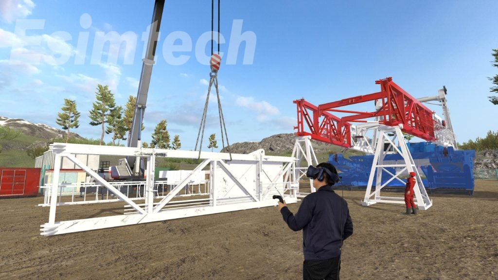
In the dynamic realm of the oil and gas sector, the application of land rig installation animation continues to reshape and revolutionize various facets of operations. Utilizing computer-generated imagery (CGI), this technology creates immersive and visually captivating animations that vividly portray the entire process of installing land rigs. But what exactly is land rig installation animation, and how does it benefit the industry? In this article, we will delve into the intricacies of this innovative technology and explore its profound significance in the oil and gas industry.
Understanding Land Rig Installation Animation
Land rig installation animation is a digital visualization approach that harnesses the power of computer-generated imagery (CGI) to replicate and elucidate the intricate process of preparing a land rig for drilling operations. It offers a comprehensive visual representation of each stage of rig installation, from initial site preparation to the meticulous arrangement of equipment. These animations are typically crafted using sophisticated computer software and are grounded in precise engineering data and standards.
The fundamental objective of land rig installation animation is to enhance comprehension, communication, and decision-making throughout the rig installation process. By generating a virtual environment, this technology provides stakeholders with a detailed and immersive experience, enabling them to envision the entire installation procedure from start to finish. This visual representation empowers stakeholders to gain a holistic understanding of the project, identify potential challenges, and make informed decisions regarding design, logistics, and safety.

Key Benefits of Land Rig Installation Animation
1. Enhancing Safety and Training
Among the most significant advantages of land rig installation animation is its capacity to boost safety. The oil and gas industry inherently poses risks, making the assurance of worker safety paramount. By recreating the installation process, these animations allow operators, engineers, and other stakeholders to identify potential safety hazards and develop mitigation strategies. This proactive approach to safety reduces the likelihood of accidents or incidents during the installation process, safeguarding both lives and assets.
Moreover, land rig installation animation serves as a valuable training tool for rig operators. These animations can simulate various scenarios, such as equipment failures or emergency situations, creating a lifelike training environment. This enables rig personnel to become familiar with the installation process, understand their roles and responsibilities, and acquire the necessary skills to effectively address unforeseen challenges. The result is a more skilled and confident workforce, which enhances safety outcomes through improved training and preparedness.
2. Optimizing Design and Planning
Another pivotal feature of land rig installation animation is its ability to optimize design and planning. Rig installations entail complex engineering considerations, including equipment compatibility, geographical constraints, and operational efficiency. The animations provide engineers and designers with a visual representation of the proposed rig design, enabling them to assess multiple configurations, identify potential bottlenecks, and fine-tune the arrangement for peak performance. This early identification of design issues or logistical challenges allows for prompt adjustments, leading to smoother installation processes and superior operational outcomes.
3. Improving Communication and Stakeholder Engagement
Furthermore, land rig installation animation enhances communication and engagement among stakeholders. These animations offer a clear and concise visual language that is easily understood by all parties involved, regardless of their technical expertise. This fosters collaborative decision-making by facilitating effective communication among engineers, operators, investors, regulators, and other stakeholders. The animations aid stakeholders in grasping the intricacies and hurdles of rig installation, ensuring that everyone shares a common understanding and works toward a unified goal.
4. Increasing Efficiency and Cost-effectiveness
Land rig installation animation offers substantial cost-effectiveness advantages. Engineers can pinpoint areas where time and resources can be conserved through visualizing the installation process, resulting in more efficient workflows and cost savings. Additionally, the animations assist in identifying the optimal placement of equipment, reducing the need for costly repositioning or modifications during installation. Moreover, by enabling early detection of design or logistical issues, these animations help prevent costly delays and revisions, ultimately leading to significant cost savings for the project.
5. Supporting Remote Operations and Global Collaboration
In an era marked by remote operations and global collaboration within the oil and gas industry, land rig installation animation shines as a valuable asset. Because the animations are virtual, geographically dispersed teams can collaborate effectively regardless of their physical locations. These animations facilitate seamless communication and collaboration among multinational teams, whether they are discussing designs, conducting virtual meetings, or troubleshooting issues. This feature not only enhances productivity but also allows companies to tap into a diverse talent pool without being constrained by geographical limitations.
In Conclusion
Land rig installation animation emerges as a potent tool that has ushered in a transformation within the oil and gas industry. It elevates safety, enriches training, optimizes design and planning, streamlines communication, bolsters productivity, and supports remote operations and collaboration by offering a virtual insight into the land rig installation process. As the industry continues to embrace digitalization and automation, land rig installation animation stands as a pivotal tool for stakeholders to make informed decisions, enhance operations, and achieve superior outcomes. It represents a breakthrough that underscores the potency of visualization and its potential to reshape traditional practices in the oil and gas sector.
Bolts are fundamental components in construction, manufacturing, and various industries, and the choice of material for bolts is critical to their performance and durability. Among the many materials used for bolts, carbon steel and stainless steel are two common options. This article aims to highlight the distinctions between carbon steel bolts and stainless steel bolts.
1. Material Composition:
Carbon Steel Bolts:
Carbon steel is primarily an iron-carbon alloy with a carbon content ranging from 0.0218% to 2.11%. The hardness and strength of carbon steel increase with higher carbon concentrations, but plasticity decreases.
Carbon steel may contain small amounts of silicon, manganese, sulfur, and phosphorus.
Carbon steel is categorized into carbon structural steel, carbon tool steel, and free-cutting structural steel based on intended use.
Stainless Steel Bolts:
Stainless steel is primarily composed of iron, chromium (Cr), and nickel (Ni). Other elements like molybdenum, titanium, nitrogen, and copper may also be present in varying proportions.
The minimum chromium content required for stainless steel is 10.5%. Different stainless steel grades have varying levels of chromium and nickel, contributing to their corrosion resistance and other properties.
Stainless steel is classified into several types, including ferritic, austenitic, austenitic-ferritic duplex, and martensitic stainless steel, each with unique characteristics.
2. Use Environment:
Carbon Steel Bolts:
Carbon steel bolts are commonly used in conventional environments, such as construction, furniture, and general manufacturing applications.
Stainless Steel Bolts:

Stainless steel bolts are preferred in environments with high corrosion potential, extreme temperatures (both high and low), and exposure to corrosive substances. Industries like medical equipment and food processing rely on stainless steel bolts due to their corrosion resistance and hygiene factors.

3. Cost Considerations:
Stainless steel is generally more expensive than carbon steel due to its superior corrosion resistance and durability.
Carbon steel, while cost-effective, may require additional measures to protect against corrosion.
4. Magnetic Properties:
Carbon Steel Bolts:
Carbon steel is magnetic and can be attracted by magnets.
Stainless Steel Bolts:
The magnetic properties of stainless steel vary depending on the specific grade. Ferritic and martensitic stainless steel are magnetic, whereas austenitic stainless steel is non-magnetic. Heat treatment can alter the magnetic characteristics of stainless steel.
5. Appearance:
Carbon Steel Bolts:
Carbon steel bolts appear darker in color, reflecting the iron content in the alloy.
Stainless Steel Bolts:
Stainless steel bolts have a silver and bright appearance due to the presence of chromium and nickel.
In summary, the choice between carbon steel bolts and stainless steel bolts depends on the specific requirements of the application. Carbon steel bolts are cost-effective and suitable for many conventional uses, while stainless steel bolts excel in environments where corrosion resistance and durability are paramount. Understanding the differences between these materials is essential for selecting the right bolts to ensure the integrity and longevity of a project or product.
Biochemical incubators are invaluable pieces of laboratory equipment, serving vital roles in scientific research and education across various fields, including plant biology, microbiology, genetics, medicine, and environmental protection. These versatile devices are equipped with a two-way temperature adjustment system, enabling precise temperature control, a critical factor for successful experiments. Biochemical incubators find applications in biology, genetic engineering, medicine, environmental research, agriculture, and more. In this article, we'll delve into the essential aspects of installing and maintaining a biochemical incubator.

Installation of a Biochemical Incubator:
Power Supply:
Ensure that the biochemical incubator is connected to a reliable 220V/50Hz power supply. A grounded power supply circuit is essential for safe operation.
Location and Ventilation:Place the biochemical incubator in a well-ventilated and dry room, away from direct sunlight. Maintain a minimum distance of 10 centimeters between the incubator and the wall to allow proper airflow.
Stability:
Adjust the base of the incubator using the bottom adjusting screw to ensure stable positioning.
Power On:
Turn on the power switch, setting it to the "on" position. The incubator will enter the powered-on state, allowing temperature and time settings.
Time Setting:
To set the time, press the temperature/time key once to activate the time setting indicator. Use the set key to enter the time setting mode, and adjust the time as needed using the ∧ and ∨ keys. Press the set key again to save the desired time setting.
Temperature Setting:
Press the temperature/time key once more to activate the temperature setting indicator. Similar to time setting, use the set key to enter the temperature setting mode, adjust the desired temperature using the ∧ and ∨ keys, and save the setting with the set key.

Maintenance of the Biochemical Incubator:
Avoid Frequent Value Changes:
To prevent frequent compressor starts and potential overloads, refrain from frequently changing the set values during use.
Lighting Switch:When lighting is unnecessary inside the incubator, switch off the lighting to maintain a stable upper-layer temperature and extend the lamp's lifespan.
Transportation Precautions:
During transportation, never place the incubator upside down or at an angle greater than 45 degrees to avoid damage.
Fuse Check:
The incubator is equipped with two sets of fuses. In case of operational issues, disconnect the power, check the fuses' condition, and then proceed with further troubleshooting if needed.
Power Off During Non-Use:
When not in use, keep the incubator dry and disconnect the power supply to conserve energy.
Axial Flow Fan Maintenance:
Regularly check the axial flow fan inside the incubator for proper operation to ensure uniform temperature distribution. Avoid overcrowding the incubator with items and ensure the fan's air outlet remains unblocked during experiments.
Avoid Physical Contact:
Avoid physical contact with the temperature sensor inside the incubator, as it can disrupt temperature control.
Cleaning:
To maintain the incubator's appearance, refrain from using corrosive solutions on its exterior. Use a dry cloth or alcohol to clean the interior, ensuring it remains free from contaminants.
In conclusion, the proper installation and maintenance of a biochemical incubator are crucial for ensuring accurate and consistent results in various scientific and research applications. By following these guidelines, researchers can maximize the functionality and lifespan of this essential laboratory equipment.
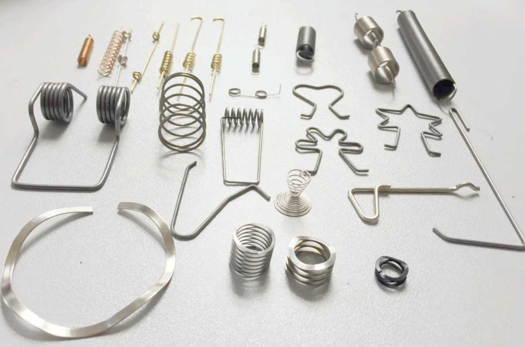
Springs are mechanical components that harness elasticity to perform various functions. They are widely employed in both the mechanical and electronics industries, offering a versatile means of converting mechanical energy into deformation energy and vice versa. Springs exhibit the remarkable property of elastic deformation when subjected to loads, reverting to their original state upon unloading. The stiffness of a spring, often referred to as its spring constant, is determined by the ratio of the load applied to the resulting deformation. Higher stiffness indicates a firmer spring.
Functions of Springs
Springs serve a multitude of functions in various applications:
Cushioning and Damping: Damping springs beneath vehicles and trains, as well as buffer springs in different types of buffers, absorb and dissipate energy to provide a smooth and controlled motion.
Mechanism Control: Springs like valve springs in internal combustion engines and clutch control springs play a pivotal role in regulating the movement of mechanical systems.
Energy Storage and Release: Devices such as clock springs and gun latch springs are designed to store energy and release it as needed.
Force Measurement: Springs are utilized in force measurement instruments like spring scales and dynamometers.
Manufacturing of Springs
The manufacturing process of springs involves several key steps:
Rolling: Large-scale production often employs universal automatic roll spring machines for rolling.
Hook Fabrication: For small-scale or custom production, springs can be made on general lathes or crafted by hand.
Fine Finishing: Precision finishing is essential to ensure the spring meets the required specifications.
Heat Treatment: The spring undergoes heat treatment, typically including quenching and medium-temperature tempering.
Performance Testing: Quality control involves rigorous testing of the spring's surface, ensuring it is free from defects such as scars and decarburization.
For springs with wire diameters less than or equal to 8mm, the cold coiling method is commonly used. When the diameter exceeds 8mm, the hot coiling method is adopted, with the coils heated to temperatures ranging from 800°C to 1000°C.

Causes of Spring Failure
Understanding the factors that can lead to spring failure is essential:
Plastic Deformation: When external loads exceed the material's yield strength, permanent plastic deformation can occur, preventing the spring from returning to its original shape and size.
Fatigue Fracture: Repeated alternating stress can lead to the development of surface defects and fatigue-induced cracks.
Rapid Brittle Fracture: Material or processing defects, heat treatment issues, or high-impact loads can result in sudden brittle fractures.
Corrosive Medium: Springs used in corrosive environments may experience stress corrosion cracking, while high-temperature applications can lead to creep and stress relaxation, causing permanent deformation.
Precautions for Springs
In practical applications, compression springs should maintain their working length even when subjected to forces beyond the material's elastic limit. To ensure this, the finished spring's length should equal the calculated length of the spring plus the initial compression volume. Additionally, during heat treatment, especially for springs requiring quenching and tempering, care should be taken to prevent spring shortening due to its weight.
Spring Deformation Applications: Spring Collets
One notable deformation application of springs is the spring collet, also known as a spring sleeve. Spring collets offer rapid and highly accurate positioning, facilitating the secure clamping of workpieces. Their advantages include:
Small Diameter Compatibility: Ideal for processing small-diameter workpieces.
Fast Loading and Unloading: Enables swift workpiece changes.
Short Replacement Times: Allows quick swapping of fixtures of varying sizes.
High Clamping Accuracy: Offers precision exceeding that of chucks.
Cost Efficiency: Reduces costs and enhances flexibility compared to chucks.
Enhanced Processing: Ideal for machine tools with internal interpolation spindle structures, providing greater processing space and rigidity.
Surface Protection: Safeguards workpiece surfaces and delivers superior cutting torque.
In conclusion, springs are indispensable components across various industries, performing an array of vital functions. Understanding their applications, manufacturing processes, and considerations ensures their effective utilization in mechanical and electronic systems. The spring collet, a deformation application, exemplifies how springs can offer high precision and versatility in specific applications.