In industries characterized by continuous material processing—such as printing, converting, packaging, and textiles—meticulous control of web tension and web alignment is paramount. These controls are essential to ensure product quality and optimize production efficiency. This article delves into the integration of web tension controllers with automated web guiding systems, shedding light on the advantages and diverse applications of this innovative combination.
Understanding Web Tension Controllers
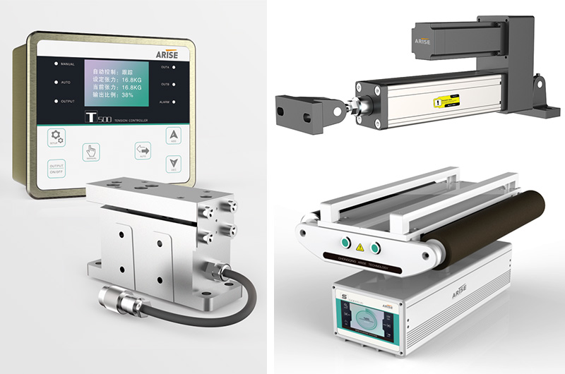
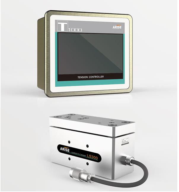
Web tension, often associated with materials in roll form or web format, pertains to the uniformity and consistency of material as it traverses the manufacturing process. Maintaining precise web tension is critical to prevent defects, control printed materials accurately, and avert web breakages. Web tension controllers are instrumental in achieving and sustaining the desired level of tension. These controllers operate by modulating the speed or torque of components like motors, brakes, or clutches to maintain the material's tension within the specified range.
The Role of Web Guiding Systems
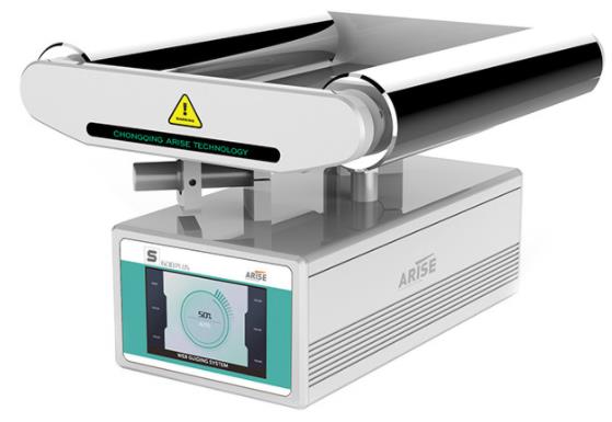
Web guiding systems are specialized machines dedicated to ensuring the alignment and positioning of continuous webs of materials as they progress through various industrial machines and processes. These materials can encompass paper, film, fabric, metal, and more. Web guiding systems are pivotal in keeping web materials centered, aligned, and free from defects as they traverse the production line.
Web guide control systems find application in numerous industrial processes where precise alignment and management of continuous materials or webs are indispensable for maintaining product quality and process efficiency. These systems play a critical role across a wide spectrum of industries, including printing, converting, packaging, textiles, and paper manufacturing.
Key Components of Web Guiding Systems
Web Sensors: These sensors detect the position or alignment of the web material. Common web guide sensors include edge sensors, line sensors, or contrast sensors, selected based on the material type and process.
Controller: The web guiding controller processes sensor inputs and determines the necessary adjustments to maintain proper web alignment. It then transmits control signals to actuators.
Actuating Devices: Actuators, such as steering guides, rollers, or moving frames, physically alter the position of the web material in response to the controller's directives.
User Interface: Some web guiding machines provide user interfaces, enabling operators to configure parameters, monitor system performance, and make manual adjustments as needed.
Advantages of Integrated Web Tension Controllers with Web Guiding Systems
The integration of web tension controllers with automated web guiding systems offers several notable advantages:
Precise Control: The combination delivers real-time tension control and ensures precise alignment and tracking of materials, resulting in high-quality finished products.
Reduced Waste: By preventing misalignment and over-tensioning, these integrated systems minimize material waste, reducing defects and web breakages.
Enhanced Efficiency: Automation reduces the need for manual interventions, enhancing overall productivity as operators can focus on other critical aspects of the manufacturing process.
Improved Product Quality: Consistent tension and alignment throughout the process significantly enhance the quality of finished products, whether it involves printing, laminating, coating, or slitting.
Versatility: These systems are adaptable and can integrate seamlessly into various machines and processes, making them suitable for a wide range of industries and applications.
Common Applications of Integrated Web Tension Controllers with Web Guiding Systems
Printing: Precise tension and alignment control are pivotal in the printing industry to produce accurately printed materials with high quality.
Packaging: Integrated systems ensure proper cutting, folding, and sealing of package materials, reducing waste and optimizing packaging quality.
Textiles: Textile manufacturers rely on these integrated systems to maintain consistent tension and alignment of fabrics, preventing defects and improving the quality of end products.
Converting: In the converting industry, where materials undergo transformation into various products, integrated systems ensure accurate and efficient processing at each stage.
Labeling: Precision web tension and web guiding are critical in label printing and application to achieve correctly positioned and securely attached labels on items.
Conclusion
The integration of web tension controllers with web guiding systems marks a significant technological advancement in manufacturing. In diverse industries, these integrated systems play a pivotal role in enhancing efficiency, reducing waste, and elevating product quality. As technology continues to advance, we can anticipate further innovations in web tension and web guiding control, driving the manufacturing industry toward increased automation and precision.
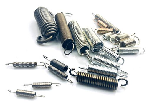
Tension springs are a type of helical spring designed to withstand axial tension. When these springs are at rest, their coils are typically tightly wound with no visible gaps. In this article, we will delve into the materials commonly used to manufacture tension springs, the essential parameters to consider before production, and the intricate production process of these invaluable components.
Materials Utilized in Tension Springs
Materials for tension springs fall into two primary categories: metallic and non-metallic.
Metallic Materials:
Spring Steel:
Carbon Spring Steel: Common grades include 65Mn, T8, T9, etc.
Alloy Spring Steel: Typical grades comprise 50Crv, 55CrSi, 60Si2Mn, etc.
Stainless Steel for Spring: Typical grades involve 304, 12Cr18Ni9, 07Cr17Ni7AI, etc.
Copper Alloys: These encompass silicon bronze, beryllium bronze, brass, among others.
Nickel and Nickel Alloys: Varieties include pure nickel, nickel-copper alloy, nickel-cobalt alloy, nickel-chromium alloy, etc.
Other Special Alloys: High-speed tool steel, alloys tailored for elastic components, memory alloys, and more.
Common Non-Metallic Materials:
Gas and Liquid:
Gas (e.g., gas spring)
Liquid (e.g., oil)
Gas-Liquid Mixtures
Rubber and Plastic Fiber Reinforcement Materials.

Key Parameters of Tension Springs
Before designing and manufacturing tension springs, it's essential to consider several critical parameters, including:
Hardness
Wire Diameter
Coil Pitch
Inner Diameter
Outer Diameter
Length
The Production Process of Tension Springs
The production process of tension springs involves a series of meticulous steps:
Winding Forming:
Cold Rolling Method: Used for springs with wire diameters (d) ≤ 8mm. Typically, quenching treatment is not performed after winding; only low-temperature tempering is required to eliminate internal stress.
Hot Rolling Method: Employed for springs with wire diameters (d) > 8mm. These springs rolled in a hot state, require quenching and tempering at medium temperature after rolling.
Heat Treatment:
Most elastic parts undergo heat treatment post-forming to establish and maintain elasticity, making it a crucial step in spring production.
End Surface Treatment:
The end surface of the spring, rolled after forging and flattening at both ends of the material, needs grinding to stabilize the support surface of the spring end ring. This ensures verticality and roughness requirements are met.
Surface Treatment:
Surface treatment options include plating (e.g., galvanized, cadmium-plated, copper-plated), bluing or blackening through oxidation treatment, phosphating (creating a water-insoluble phosphate film on the metal surface), and protective coatings such as paint, asphalt, or plastic.
Packaging and Storage:
Manufactured tension springs are meticulously packaged in specialized containers designed to protect them during transportation and storage.
Conclusion
The production of tension springs involves careful consideration of materials, parameters, and an intricate manufacturing process. KENENG, a trusted enterprise in spring production, offers a range of spring types, including compression springs, tension springs, mold springs, and special-shaped springs, all customized to meet customer specifications. With a rich history in the industry, KENENG is committed to delivering high-quality, cost-effective springs tailored to your unique needs. If you require springs, reach out to KENENG for top-notch service and quality products.
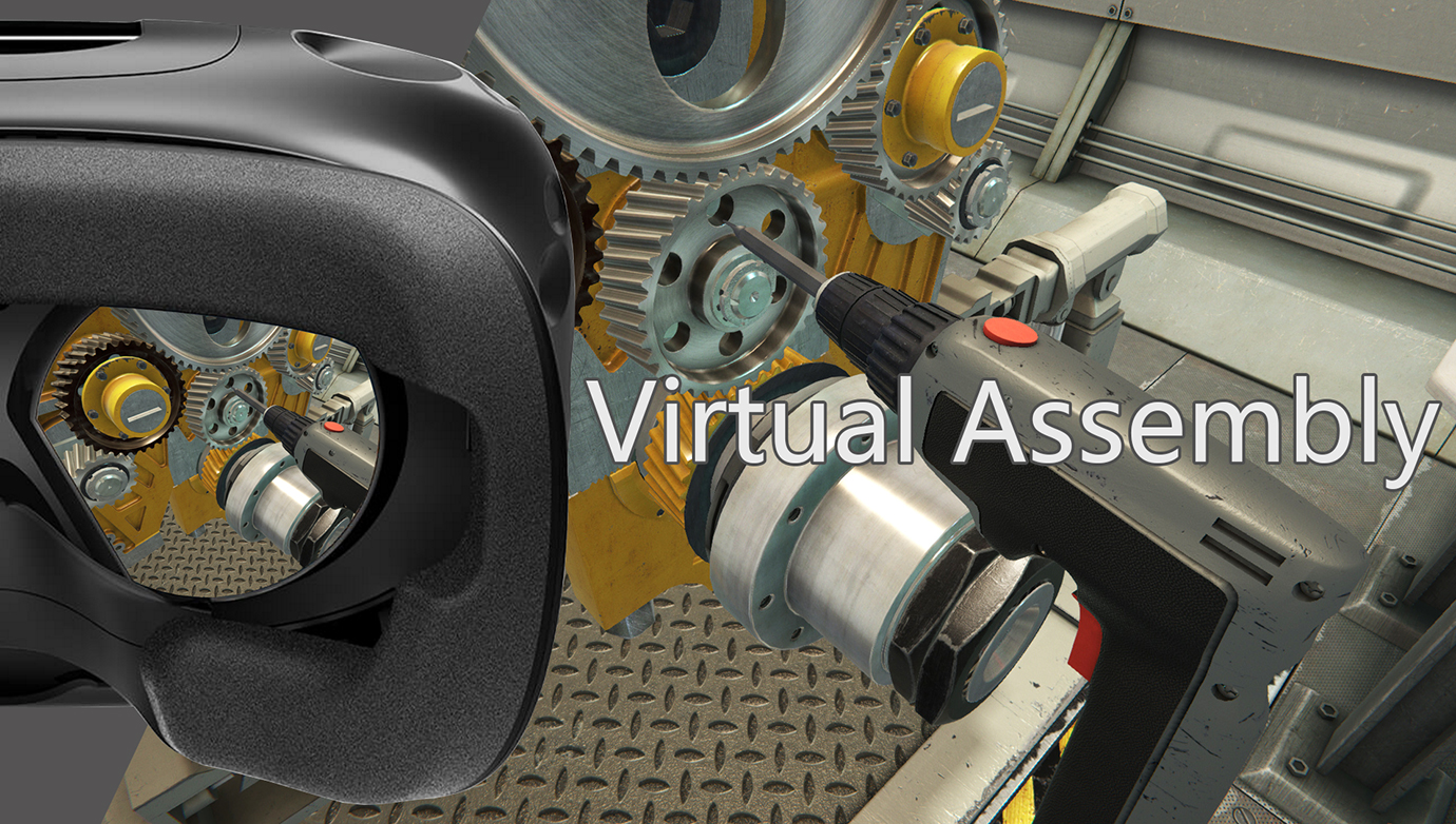
The Device Virtual Assembly Simulator (DVAS) is a cutting-edge virtual reality (VR) application revolutionizing the manufacturing industry. It offers manufacturers the ability to replicate and fine-tune assembly processes virtually, leading to enhanced efficiency, reduced costs, and superior product quality. This article delves into the concept of DVAS, its significance, operational mechanisms, advantages, and its profound impact on manufacturing.
Why DVAS is Crucial for the Manufacturing Sector
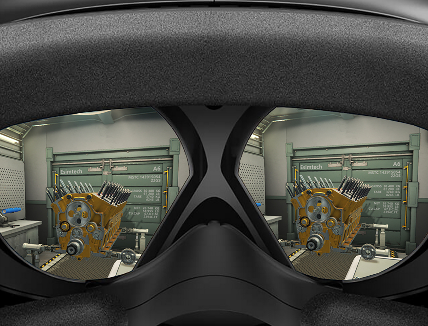
DVAS is a computer-based system that leverages virtual reality and simulation technologies to replicate assembly operations. Manufacturers can create virtual prototypes of equipment or products, allowing them to simulate assembly, disassembly, and maintenance processes. Users interact with virtual objects using specialized VR equipment such as headsets and motion controllers, resulting in a highly immersive experience.
How DVAS Operates
DVAS seamlessly integrates multiple technologies to deliver a unified virtual assembly experience:
3D Modeling: Manufacturers initiate the process by developing 3D models of their equipment or products using Computer-Aided Design (CAD) software. These digital models serve as the foundation for the virtual assembly simulation.
Physics Simulation: DVAS employs physics-based techniques to simulate the physical behavior of objects in a virtual environment. Factors like gravity, collisions, and interlocking systems are meticulously replicated. This ensures the realism and accuracy of the assembly process.
Virtual Environment: The DVAS recreates actual manufacturing facilities within a virtual environment, complete with workstations, tools, and other components essential for assembly. Users can navigate and interact with this virtual space using specialized VR devices.
Assembly Process: Manufacturers engage with virtual components using motion controllers to virtually assemble equipment or products. The system tracks users' movements and gestures, allowing them to manipulate virtual objects as if they were physically assembling them. This immersive experience fosters realism.
Real-time Feedback: DVAS provides real-time feedback during the assembly process. Visual indicators, tactile feedback, or audio signals guide users, ensuring adherence to correct assembly methods. This feedback aids users in analyzing and optimizing their assembly procedures for enhanced efficiency.
Disassembly and Maintenance: In addition to assembly, DVAS supports virtual disassembly and maintenance activities. Users can practice and refine their disassembly, maintenance, and reassembly skills without risking damage to real-world objects or equipment.
Iterative Refinement: Manufacturers can iterate and refine the assembly process within the virtual environment using DVAS. This enables early detection and correction of issues or inefficiencies, optimizing the assembly process before actual manufacturing. Such iterative refinement saves time, reduces costs, and enhances overall product quality.
Benefits of DVAS
Improved Efficiency: DVAS eliminates the need for physical prototypes and reduces trial-and-error assembly, allowing manufacturers to identify and rectify issues early in the design phase, thus streamlining the assembly process and shortening time-to-market.
Cost Reduction: Traditional assembly methods can be costly due to physical prototypes, material waste, and rework. DVAS detects and rectifies errors online, reducing the need for physical iterations and lowering costs.
Enhanced Product Quality: DVAS enables comprehensive evaluation of the assembly process, ensuring precise component fit and intended performance. This results in improved product quality and customer satisfaction.
Training and Skill Development: DVAS provides a safe training environment for assembly line workers. New personnel can learn and practice assembly techniques without risking damage to products or equipment. It also facilitates skill development and evaluation for continual improvement.
Design Optimization: DVAS identifies design defects or inefficiencies early on, allowing designers to optimize product design for improved manufacturability and reduced production costs.
Data Analytics: DVAS records and analyzes valuable data during the virtual assembly process. This data can be used to enhance overall production processes, providing insights into productivity, identifying bottlenecks, and optimizing assembly line layouts.
Future Prospects and Challenges
DVAS holds immense potential for the future of manufacturing. As VR technology advances, the simulation experience will become increasingly realistic. Integration with artificial intelligence and machine learning algorithms may enable the system to provide intelligent suggestions and automate repetitive processes.
However, challenges such as the initial setup cost and ensuring the accuracy of virtual simulations compared to real-world processes must be addressed through collaboration among technology developers, manufacturers, and researchers.
In Summary
The Device Virtual Assembly Simulator (DVAS) is a pivotal innovation in manufacturing, employing virtual reality and simulation technology to enhance efficiency, reduce costs, and improve product quality. As technology continues to evolve, DVAS will play a vital role in shaping the future of manufacturing, enabling companies to streamline processes, train their workforce effectively, and achieve higher levels of efficiency and competitiveness.
Polarimeters are indispensable instruments in various industries for measuring the optical rotation of optically active substances. By quantifying the optical rotation of a sample, one can glean valuable insights into its concentration, content, and purity through meticulous analysis. In this guide, we'll delve into the principles of polarimeters and eight crucial considerations to bear in mind when buying one.

Principles of Polarimeters
Polarimeters function by manipulating polarized light. Initially, natural light is transformed into plane-polarized light as it passes through a polarizer. When an optically active substance is introduced into this polarized light, it causes the angle of the light to rotate either to the left or right by a specific degree. The rotated polarized light subsequently passes through an analyzer grating, requiring the analyzer to be adjusted to a certain angle to yield a bright light at the eyepiece. This angle of rotation represents the optical rotation of the substance being tested.
Eight Key Considerations When Buying a Polarimeter
Industries Using Polarimeters: Polarimeters find wide applications in the food, chemical, pharmaceutical, flavor, and fragrance industries.
Important Purchase Indicators: The primary indicators to focus on when purchasing a polarimeter are accuracy and repeatability. The sensitivity of the instrument can be gauged by sample transmittance, with a transmittance of 1% indicating relative sensitivity. For temperature-controlled polarimeters, precision in temperature control is crucial, and if it falls short, a water bath can be employed for control.
Sodium Lamp vs. LED as Light Source: Both sodium lamps and LEDs can be used as light sources for polarimeters. While sodium lamps have a limited lifespan (50 to 200 hours), LEDs boast a considerably longer life of over 5,000 hours and are more cost-effective when compared to sodium lamps. LEDs can also be tuned to match the 589.3nm wavelength of sodium lamps.
Samples Requiring Temperature Control: Temperature affects the optical rotation of all substances. While some substances have predefined temperature coefficients (e.g., sugar), others lack them, necessitating precise temperature control. Compliance with Good Manufacturing Practices (GMP) also dictates strict temperature requirements.
Benefits of Automatic Calibration: Polarimeters equipped with automatic calibration functions ensure continuous instrument performance monitoring and prompt adjustments, ensuring optimal functionality.
Measurement Modes: Polarimeters offer four primary measurement modes: optical rotation, specific rotation, concentration, and sugar content. Some advanced models allow users to effortlessly switch between these modes, eliminating the need for complex calculations.
Calibration Frequency: Calibration frequency should align with usage and accuracy requirements. Users can choose to calibrate weekly or monthly, or even daily using a quartz standard polarimeter if a specific angle of measurement is consistently employed.
Environmental Impact: Maintaining a stable room temperature around 20 degrees Celsius is advisable, even when conducting temperature-controlled measurements. The optimal working environment for polarimeters typically falls within the range of 15-25 degrees Celsius, as significant temperature variations between the ambient and testing temperatures can lead to inaccurate results.
In conclusion, a thorough understanding of the principles of polarimetry and careful consideration of the factors outlined above are essential for making an informed decision when purchasing a polarimeter. This versatile instrument plays a pivotal role in various industries, aiding in precise measurements and quality control processes.
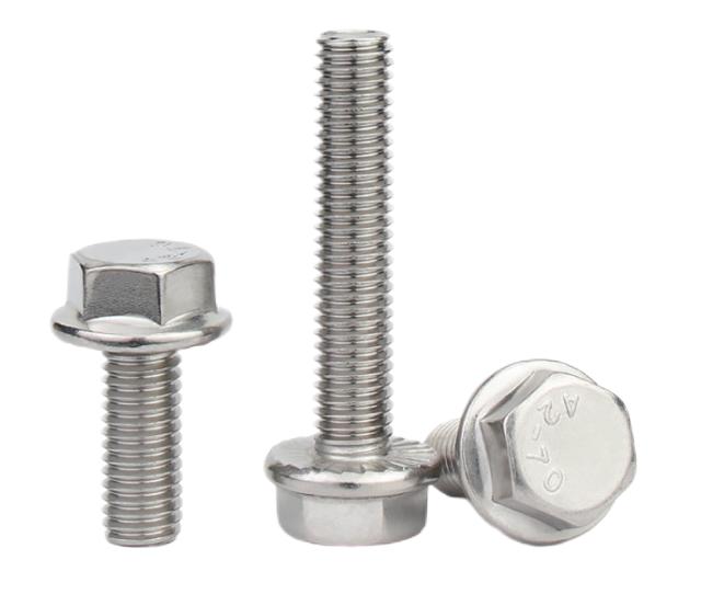
The quality of bolt assembly and the precision of bolt tightening are crucial elements in the entire process of automobile assembly. This article delves into the significance of the bolt tightening process during vehicle assembly and its mechanical analysis. Understanding the importance of this process is essential for ensuring the structural integrity and safety of automobiles.

Mechanical Analysis of Bolt Tightening:
During the bolt tightening process, bolts undergo stretching and deformation due to tensile forces while engaging in a compressive interaction with connectors through threaded fasteners. The forces applied to the bolts and connectors are equal in magnitude and opposite in direction.
At this stage, the force exerted by the bolt on the connected part is referred to as the axial preload of the bolt. The force changes in several stages during bolt tightening. Initially, when the bolt head does not make contact with the fastener, compression force is zero, and torque is minimal.
As the bolt head aligns with the fastener, further tightening leads to a gradual increase in compression force and torque. Continued tightening results in the compression force and torque reaching a plateau, as the bolt nears its yield point. Once this yield point is reached, further tightening leads to reduced tightening force and torque, potentially causing deformation or fracture of the bolt.
Bolt Tightening Methods:
Three primary bolt tightening methods are used in automobile assembly:
Torque Control Method:
This method relies on the linear relationship between axial clamping force (F) and tightening torque (T), expressed as T = K * F.
It is cost-effective, utilizing a torque wrench for quality checks.
However, it may lack precision and is susceptible to environmental factors.

Torque Angle Control Method:
This method involves initial tightening to a fraction (typically 40% to 60%) of the full torque, followed by tightening to a specified angle.
It provides high control precision and generates substantial axial clamping force.
The downside is the complexity of the control system and the need for precise measurement of pre-tightening torque and angle.
Yield Point Control Method:
This method tightens bolts until they reach their yield point.
It ensures reliable clamping force but requires careful monitoring to prevent over-tightening.
Dynamic Torque vs. Static Torque:
Dynamic torque is measured during the tightening process, ensuring that the axial preload meets engineering requirements.
Static torque, measured after tightening, is used to monitor production process stability.
Tool Selection for Bolt Tightening:
Tool selection is influenced by production capacity, assembly complexity, and assembly process layout.
The decision between power tools and manual tools is based on actual assembly needs and the complexity of the product.
Early planning and design of the bolt tightening process are essential to prevent assembly abnormalities and enhance product quality.
Conclusion:
Bolt tightening is a critical aspect of automobile assembly, impacting structural integrity and safety. Properly executed bolt tightening ensures the stable operation of the production line, improves economic benefits, and enhances product quality while reducing development costs. Understanding the mechanics of bolt tightening and selecting the appropriate tools are pivotal for achieving these goals in the automotive assembly process.