Spray dryers and freeze dryers are both essential instruments in the world of substance drying, each with distinct applications and equipment features. This article aims to elucidate the disparities between spray dryers and freeze dryers and highlight their respective advantages.
Spray Drying
Spray drying is a systematic technology used for material drying. In this method, a liquid solution or emulsion is atomized within a drying chamber. As the fine mist of liquid encounters hot air, rapid water evaporation occurs, yielding a dry product. This process can directly transform solutions and emulsions into powders or granular products, eliminating the need for separate evaporation, crushing, and other processes.
The fundamental principle involves dispersing the material into ultra-fine particles resembling mist through mechanical means, thus increasing the water's evaporation surface area and hastening the drying process. Most of the water is instantly removed upon contact with hot air, leaving the solid components dry in powder form.

Spray drying operates at high temperatures, enabling swift moisture evaporation and producing a superior drying effect. Simultaneously, the resulting particles are relatively uniform in size and possess excellent flow properties.
This method is particularly beneficial for preserving the nutritional value of substances that are heat-sensitive. In cases where high temperatures are necessary to eliminate specific substances, such as trypsin inhibitors in soybeans, spray drying technology is an ideal choice. The process effectively converts liquids into powders while preserving the taste, color, and nutritional content of food, all while removing microbial contamination.
Apart from moisture removal, spray drying has various other applications, including altering substance size, shape, or density, facilitating ingredient addition in production processes, and aiding in the creation of products adhering to strict quality standards. Notably, fruit and vegetable powders produced via spray drying retain the nutritional content of fresh produce while reducing volume for convenient consumption and transportation.
For reference, here's a nutritional comparison between fresh pumpkin and spray-dried pumpkin powder:
Drying technology varies between high-temperature and low-temperature drying. While spray drying employs high-temperature spraying, there are situations where low-temperature freeze-drying, or freeze drying, is a more appropriate choice.
Advantages of Freeze Drying
Freeze drying, also known as sublimation drying, involves freezing a water-containing material below its freezing point, turning the water into ice, and subsequently transforming the ice into vapor under a high vacuum to remove it. Materials can either be pre-frozen and then dried or frozen directly within the drying chamber under rapid evacuation. The water vapor resulting from sublimation is removed via a condenser, with the necessary heat for vaporization supplied through thermal radiation.
The fundamental principle of laboratory freeze dryer capitalizes on the three phases of water, where point O signifies the common point of all three phases and OA represents the melting point of ice. By reducing pressure below the triple point pressure (below 646.5Pa, at a temperature below 0°C), moisture in materials can directly transition from water to water vapor without passing through a liquid phase.
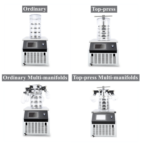
By applying this principle, wet raw materials can be frozen below their freezing point, causing moisture to solidify into ice. In a suitable vacuum environment, this ice is then sublimated directly into vapor, with the water vapor being condensed by a condenser, thus achieving effective drying.
Freeze drying offers several advantages:
Suitability for Heat-Sensitive Substances: Operating at low temperatures makes freeze drying ideal for preserving the integrity of heat-sensitive materials such as proteins and microorganisms, ensuring they do not denature or lose biological activity.
Minimal Loss of Volatile Components: The low-temperature drying process minimizes the loss of volatile components in substances, making it suitable for drying chemical products, medicines, and food items.
Preservation of Original Properties: Freeze drying prevents the growth of microorganisms and the action of enzymes, allowing the original properties of substances to be maintained.
Maintenance of Original Structure: The frozen state preserves the substance's volume and structure, preventing condensation and maintaining its original form.
Rapid Reconstitution: Freeze-dried substances, resembling sponges, dissolve quickly and revert to their original state when rehydrated.
Oxygen Protection: Drying under vacuum conditions minimizes oxygen exposure, preserving easily oxidized substances.
Long Shelf Life: Freeze drying removes over 95-99% of water, facilitating long-term storage without deterioration.
In summary, spray dryers and freeze dryers each possess unique strengths and drawbacks. Spray drying offers rapid moisture removal and uniform particle sizes but involves high temperatures. In contrast, freeze drying operates at low temperatures, preserving delicate substances, but the process can be time-consuming. The choice between the two depends on the specific needs of the application and the characteristics of the material being dried.
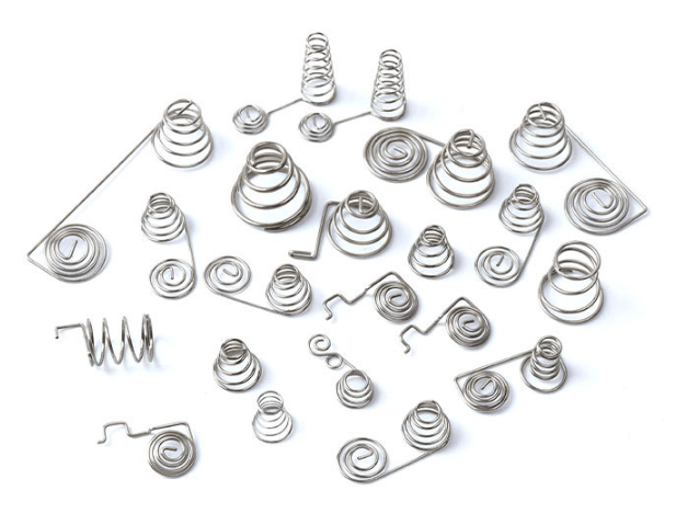
Surface treatment is a crucial aspect of spring manufacturing, aimed at preserving and protecting these vital components. Springs are often exposed to challenging environmental conditions, making it essential to employ protective layers. These protective layers of springs can be categorized into metal protective layers, chemical protective layers, and non-metallic protective layers, each chosen based on the specific needs of the application.

Metal Protective Layers for Springs
One common method of providing protection to springs is by applying a metal protective layer. Among the various techniques available, electroplating is a widely used method for obtaining a metal protective layer. Two of the most prevalent options in this category are galvanization and cadmium plating.
Non-Metallic Protection for Springs
Non-metallic protective layers are applied by dipping or spraying substances such as asphalt or paint onto the spring's surface. These layers serve as a barrier against environmental factors, safeguarding the spring from corrosion and other forms of degradation.
Chemical Protection of Springs
Chemical protection involves creating a dense protective film on the spring's surface through processes like oxidation treatment or phosphating. This film acts as a shield against corrosion and extends the spring's lifespan. Both oxidation treatment and phosphating are cost-effective methods, with oxidation treatment being the preferred choice among Spring manufacturers.
Oxidation Treatment of Springs
Oxidation treatment, also known as bluing or blackening, results in the formation of a protective magnetic iron oxide layer on the spring's surface. The color of this oxide film can vary, ranging from blue and black to dark brown. The specific hue depends on factors like the oxidation process, the spring's surface condition, and its chemical composition.
Methods of Oxidation Treatment
Oxidation treatment encompasses various methods, including alkaline oxidation, alkali-free oxidation, and electrolytic oxidation. In most cases, alkaline oxidation is the method of choice. However, it's important to exercise caution during oxidation treatment, as it can erode surface grain boundaries, potentially reducing fatigue strength.
The Process of Alkaline Oxidation
Alkaline oxidation involves immersing the spring in a sodium hydroxide solution at approximately 140°C for a specified duration. During this process, the oxidant and sodium hydroxide react with iron to produce Na2FeO2 and Na2Fe2O4, ultimately forming the protective magnetic iron oxide. The thickness of the oxide film typically ranges from 0.6 to 2 μm. Factors affecting corrosion resistance include oxide film compactness, thickness, oxidant concentration, sodium hydroxide concentration, and solution temperature.
Phosphating Treatment of Springs
Phosphating treatment entails immersing the spring in a phosphate solution containing manganese, iron, and zinc to create a water-insoluble phosphate film on the metal surface. The resulting film appears dark gray, gray, or dark gray, imparting a dull finish. Generally, the thickness of the phosphating film ranges from 5 to 20 μm.
Precautions for Phosphating Treatment
Several precautions should be taken during phosphating treatment:
Phosphating films possess microporous structures, making them ideal for paint and grease adhesion. Hence, phosphating is often combined with coating methods like painting.
Phosphating films can withstand high temperatures (400~500℃), making them suitable for springs operating in elevated temperature environments.
Springs should be sandblasted before phosphating. Immediate phosphating after sandblasting is recommended. If sandblasting equipment is unavailable, chemical degreasing and pickling can be used to remove oil.
Phosphating processes produce hydrogen, which can lead to hydrogen embrittlement in critical parts of the spring. Dehydrogenation treatment is essential after phosphating to mitigate this risk.
Production well logging is a vital operation in the oil and gas sector, offering critical insights into subsurface reservoirs. Analyzing the physical parameters of formations and fluid content is crucial for optimizing output and recovery. This article delves into the significance, characteristics, and applications of production well logging simulators in modern oil and gas operations.

The Significance of Production Well Logging Simulators
Production well logging involves collecting data from downhole tools on an oil or gas well's production string, monitoring factors like formation porosity, resistivity, fluid saturation, pressure, and temperature. This data forms the foundation for informed decisions that enhance production, improve well performance, and extend reservoir life. The production well logging simulator, capable of simulating downhole tool responses and accurately interpreting logging data, empowers operators in these endeavors.
Key Components and Features of Production Well Logging Simulators
Downhole Tool Models: These simulators include realistic representations of industry-standard downhole logging tools:
Gamma Ray (GR) Detector: Identifies lithology and estimates mineral content by measuring natural gamma radiation emitted by formations.
Resistivity Sensors: Identify hydrocarbon-bearing zones and water saturation levels by determining the formation's electrical resistivity.
Neutron Porosity Tool: Estimates porosity and distinguishes between oil, gas, and water zones by measuring hydrogen content.
Density Log: Provides lithology information and computes porosity by measuring bulk density.
Pressure Gauge: Records downhole pressure, aiding well performance evaluation and reservoir pressure analysis.
Reservoir and Fluid Models: Precise geology, petrophysical, and hydrodynamic models consider variables such as formation porosity, permeability, fluid saturation, and rock properties to simulate the subsurface reservoir accurately.
Numerical Algorithms: Advanced algorithms transform raw logging data into valuable reservoir properties, including inversion algorithms for formation characteristics and machine learning techniques for data-driven interpretations.
3D Visualization: Engineers can observe reservoir changes over time, enhancing understanding of reservoir dynamics and production effects.
Data Integration: Incorporating seismic data, historical production data, and well test results provides a holistic view of the reservoir, improving characterization and interpretation accuracy.
Uncertainty Analysis: Well logging data inherently carries uncertainties; thus, the simulator employs uncertainty analysis methods to enhance decision-making under uncertainty.
User Interface: A user-friendly interface facilitates data entry, simulation setup, and result visualization, catering to professionals with varying levels of expertise.
Scenario Analysis: Engineers can assess various production tactics' influence on reservoir performance and optimize production plans by running different scenarios.

Applications of Production Well Logging Simulators
Reservoir Management: Vital for optimizing production plans, predicting reservoir behavior, and extending reservoir lifespan.
Field Development Planning: Aids in selecting well locations, well completion designs, and overall reservoir development strategies, ensuring efficient resource utilization and maximized production potential.
Well Performance Evaluation: Helps engineers evaluate individual well performance, identify production issues, and implement corrective actions to increase output.
Enhanced Well Stimulation: Supports the design of effective well stimulation and enhanced oil recovery (EOR) procedures, increasing hydrocarbon recovery rates through accurate formation and fluid saturation calculations.
Reservoir Monitoring and Surveillance: 3D visualization enables operators to track reservoir changes, identify production difficulties, and respond promptly.
Reserve Estimation: Accurate well logging data and reservoir characterization aid in precise calculations of recoverable hydrocarbon reserves, influencing financial planning, asset valuation, and investment decisions.
Conclusion
Production well logging simulators provide engineers with invaluable data and insights into subsurface reservoirs, enabling informed decision-making and optimizing production and reservoir management. They have evolved into indispensable tools within the oil and gas industry.
X-ray diffraction (XRD) is a commonly used testing method, yet many students remain unfamiliar with its principles and applications. In this article, Drawell will provide insights into XRD, addressing various aspects of this technique.
1. Understanding the Utility of XRD
X-ray diffraction involves scattering X-rays when they interact with a material. When X-rays strike crystalline substances, they undergo coherent scattering, which is a diffraction phenomenon. This means that the incident X-ray beam changes direction without changing its wavelength upon exiting the material. This unique behavior is specific to crystalline substances.
Most solid-state materials are either crystalline, microcrystalline, or quasi-crystalline and can exhibit X-ray diffraction. The crystal's microstructure exhibits a periodic, long-range ordered arrangement. The X-ray diffraction pattern is a representation of the three-dimensional structure of the crystal microstructure, containing critical information about the crystal's composition and structure. XRD is currently the most powerful method for studying crystal structures, including atomic positions, unit cell dimensions, and more.

XRD is particularly well-suited for phase analysis of crystalline substances. Different phases or structures within crystalline substances exhibit variations in the number of diffraction peaks, their angles, relative intensities, and peak shapes. By comparing the X-ray diffraction pattern of an unknown sample with that of known crystalline substances, one can qualitatively identify the phase composition and structure of the sample. Additionally, quantitative analysis of the sample's phase composition is possible by analyzing the diffraction intensity data.
2. Distinguishing Amorphous, Quasi-Crystalline, and Crystalline Structures
Differentiating between amorphous, quasi-crystalline, and crystalline structures in XRD patterns is not always straightforward. In XRD patterns obtained from crystalline materials, you typically observe sharp, distinct peaks with narrow 2Θ widths at half-height (usually 0.1° to 0.2°). Broadened peaks suggest that the crystals in the sample have smaller particle sizes, often less than 300 nm, known as "microcrystals." The Scherrer formula can estimate the grain size based on spectral line broadening.
In contrast, amorphous materials exhibit a gentle, continuous change in X-ray scattering intensity over a wide angle range (2θ 1° to several tens of degrees), often with one or more maxima. This phenomenon occurs due to extremely fine grain sizes leading to broadened, overlapping, and blurred diffraction peaks. Quasi-crystalline materials represent a transitional state between crystalline and amorphous, characterized by unique diffraction patterns.

3. Impact of Different X-ray Targets
The choice of X-ray target, such as copper or chromium, affects the characteristic wavelengths used in XRD experiments. The diffraction angle, determined by the Bragg equation, changes with varying wavelengths. Consequently, the positions of diffraction peaks on XRD patterns obtained from different X-ray tubes will differ systematically. However, a crystal's set of d values, inherent to its structure, remains consistent, independent of the X-ray target.
The relative intensities of diffraction peaks may vary slightly when using different targets for the same sample. This variation is attributed to the absorption properties of the sample in relation to the incident X-ray wavelength and the target material.
4. Determining Crystal Planes Corresponding to Diffraction Angles
To determine the crystal planes corresponding to different diffraction angles, consult powder diffraction data cards that provide diffraction index information for each diffraction line. For unknown crystal structures, the process of determining diffraction indices for each line is known as "indexing the diffraction pattern." This step requires a foundation in crystallography and proficiency in indexing software, such as treaor90.
5. Obtaining Atomic Coordinates in Crystals
To acquire atomic coordinates within a crystal, perform single-crystal X-ray diffraction. This technique, in addition to using CCD detectors, provides precise atomic position data.
6. Calculating Grain Size, Lattice Constants, and Distortion
Grain size, lattice constants, and distortion can be calculated from X-ray diffraction data, specifically from peak shape information. When the broadening of diffraction peaks is solely due to crystal grain fineness, the Scherrer formula can estimate grain size based on the extent of peak broadening.
The above is the arrangement of the common problems of XRD. If you need an XRD test or the XRD instrument, you can contact Drawell.
Safety at sea is paramount, and having dependable life-saving equipment can make all the difference in an emergency. The davit launched liferaft is one such vital piece of maritime safety equipment. In this article, we will focus on the topic that what is a davit-launched liferaft, exploring its functions, how it works, and why it is an indispensable component of maritime safety.
Functions of a Davit Launched Liferaft
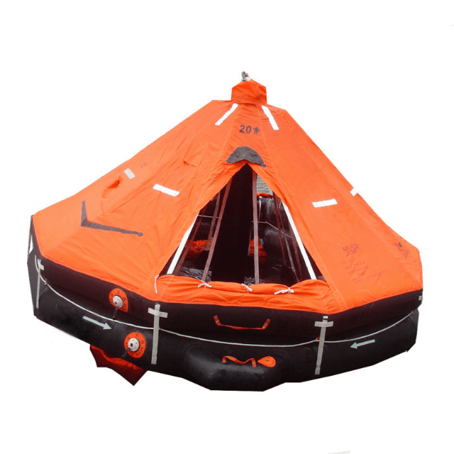
A davit launched liferaft is a specially designed inflatable life raft used on ships, offshore platforms, and other marine vessels. Its primary function is to evacuate passengers in the event of an emergency such as a ship sinking, fire, or other life-threatening circumstances. Unlike throw-overboard liferafts, davit-launched liferafts are secured on deck and launched using mechanical davit systems.
How Does a Davit Launched Liferaft Work
A davit launched liferaft operates through a series of carefully coordinated steps:
Stowage: Davit-launched liferafts are securely stored on the vessel, typically in designated compartments or containers on the deck or superstructure. These storage locations are designed to protect the liferafts from environmental elements and potential damage.
Activation: In the event of an emergency, the crew activates the release mechanism for the liferaft. This can be done manually by pulling a release handle or automatically through a hydrostatic release unit, which activates when the liferaft is submerged to a certain depth.
Inflation: Upon activation, the liferaft starts to inflate. Inflation can be achieved through either a CO2 cylinder, where the release mechanism punctures the cylinder, allowing CO2 gas to rapidly inflate the liferaft, or a combination of gas and water pressure.
Launch: Once fully inflated, the liferaft is ready for deployment into the sea. This is accomplished by a davit system, a mechanical device designed to swing the liferaft out of its stowage place and safely lower it into the sea. Crew members operate the davit system, ensuring a controlled and safe deployment.
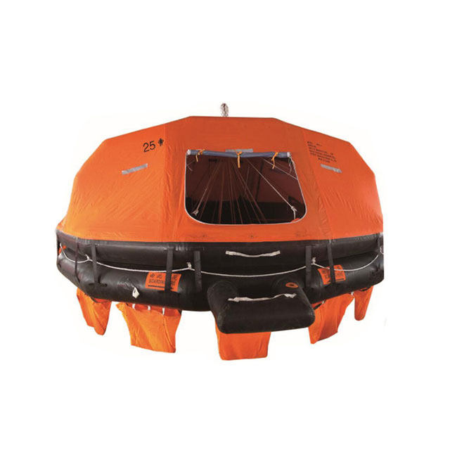
Occupancy: As the davit-launched liferaft enters the water, it stabilizes and provides a safe platform for passengers to board. These liferafts are designed to remain steady even in stormy seas and come equipped with multiple entrances, handholds, and boarding ladders for convenient access. The liferaft also contains essential survival equipment such as water, food, first aid supplies, and signaling devices.
Survival: Passengers inside the liferaft can use the provided materials to sustain themselves until rescue arrives. The liferaft is self-contained, offering protection from the elements and the means to signal for assistance using flares, radios, or other communication equipment.
Visibility: Davit launched liferafts are typically brightly colored, often in international orange or other highly visible hues. Reflective materials are also used to enhance visibility, making it easier for search and rescue teams to locate them, especially during low-light conditions or at night.
Importance of a Davit Launched Liferaft
A davit-launched liferaft is of paramount importance in the maritime industry for several compelling reasons:
Rapid Deployment: In emergency situations at sea, time is of the essence. Davit-launched liferafts can be deployed quickly, minimizing the time it takes for passengers and crew to evacuate a sinking ship or respond to other life-threatening incidents.
Safety and Stability: These liferafts are designed to provide a safe and stable platform for occupants. They remain upright and buoyant even in rough seas, high winds, and adverse weather conditions, preventing capsizing and ensuring passenger safety.
Capacity: Available in various sizes, davit-launched liferafts can accommodate different vessel types and passenger loads. This adaptability makes them suitable for a wide range of marine circumstances, from small pleasure boats to large commercial vessels.
Regulatory Compliance: International maritime regulations, notably those outlined in the SOLAS Convention, mandate the presence of davit-launched liferafts on specific types of vessels, including commercial ships and passenger vessels. Compliance underscores their importance while ensuring vessels meet stringent safety standards.
Self-Containment: These liferafts are typically equipped with essential survival supplies, including fresh water, non-perishable food, first aid kits, and signaling devices such as flares and radios. This self-containment allows passengers to sustain themselves until rescue arrives, even in remote or challenging maritime environments.
Visibility: Davit-launched liferafts are designed with high-visibility colors, often in international orange or yellow, to enhance their visibility from a distance. Reflective materials further increase visibility during low-light conditions or at night, aiding search and rescue efforts.
Reliability: These liferafts undergo rigorous testing and quality assurance to ensure their reliability in emergencies. They are built to withstand harsh environmental conditions, including exposure to seawater, UV radiation, and extreme temperatures.
Evacuation of Non-Swimmers: Especially crucial for vessels carrying passengers who may not be strong swimmers, such as children, the elderly, or individuals with limited mobility. Davit-launched liferafts offer a safe and convenient mode of evacuation for all passengers, regardless of their swimming ability.
Conclusion
A davit-launched liferaft is indispensable for maritime safety as it provides a reliable means of escape and survival during emergency situations at sea. These inflatable life rafts are designed to withstand adverse conditions and protect occupants until assistance arrives. Securely stowed on vessels and launched using mechanical davit systems, they exemplify the commitment to safety in the maritime industry.