The construction of oil rigs stands as an extraordinary testament to engineering prowess, addressing the global thirst for energy. Nestled in vast oceans, these monumental structures play a pivotal role in extracting petroleum resources, powering industries, economies, and contemporary lifestyles. This article delves into the intricate realm of oil rig construction, unraveling the methods, processes, challenges, and groundbreaking innovations that characterize the creation of these offshore marvels.

Understanding Oil Rig Construction:
Oil rig construction is a sophisticated endeavor demanding meticulous planning, cutting-edge technology, and a skilled workforce. The primary objective is to erect a resilient platform capable of withstanding the unforgiving conditions of the open sea while facilitating the extraction of oil and gas beneath the ocean floor. Two main types of oil rigs emerge: fixed platforms and floating structures.
Fixed Platforms:
Ideal for shallow waters, these rigs anchor to the ocean floor. Comprising steel or concrete bases extending from the seabed to the water's surface, fixed platforms find their niche in calm, shallow waters with a stable seafloor foundation.
Floating Structures:
Designed for deeper oceans where fixed platforms are impractical, floating rigs come in various forms like semisubmersibles, drillships, and tension leg platforms (TLPs). Leveraging buoyancy and mooring devices ensures stability in these challenging environments.
Detailed Process of Oil Rig Construction:
Oil rig construction is a collaborative achievement involving engineers, designers, technicians, and a diverse array of skilled individuals. The process unfolds through key stages:
Pre-Construction Planning and Design:
Thorough planning and design precede construction, incorporating feasibility studies and detailed engineering designs using computer-aided design (CAD) software.
Fabrication of Components:
Various components, serving distinct purposes, are fabricated off-site and then transported to the rig for assembly, including the foundation and superstructure.
Assembly and Integration:
Assembled components are integrated into the overall structure, involving the installation of foundations and superstructures with precision.
Installation of Equipment:
Drilling, extraction, and processing equipment are installed, encompassing drilling rigs, processing facilities, and crew accommodations.
Safety and Testing:
Safety Systems: Fire detection and suppression equipment, emergency shut-off valves, and evacuation routes are installed and tested on the rig.
Testing and Simulations: Various systems, including drilling operations and emergency procedures, are tested through drilling simulators to ensure readiness for operational use.

Transportation and Installation:
For floating oil rigs, the final construction is transported to its designated location in the open sea, employing advanced mooring systems for positioning.
Commissioning and Operation:
Commissioning involves final testing and adjustments, paving the way for drilling operations to extract oil and gas from the ocean floor.
Maintenance and Upgrades:
Regular maintenance and technological upgrades, incorporating automation and data analytics, contribute to the rig's efficiency, safety, and environmental performance.
Challenges and Innovations for Oil Rig Construction:
Navigating challenges inherent to offshore construction, the industry embraces innovations that enhance safety, efficiency, and environmental responsibility.

Challenges:
Harsh Environmental Conditions
Safety Concerns
Logistics
Depth and Pressure
Regulatory Compliance
Innovations:
Advanced Materials
Automation and Robotics
Digital Twin Technology
Drilling Technologies
Subsea Systems
Environmental Mitigation
Digitalization and Data Analytics
Hybrid Energy Solutions
Smart Sensors and IoT
Conclusion
Oil rig construction melds engineering expertise, technological advancements, and environmental consciousness. These colossal structures, whether fixed platforms or floating wonders, stand as indispensable contributors to meeting the world's energy demands.
In the dynamic realm of modern manufacturing, where efficiency and precision are paramount, the printing industry stands out for its need to balance high-speed output with flawless quality. The introduction of printing quality inspection systems has revolutionized the landscape of printing quality assurance, ensuring top-notch printing quality at unparalleled speeds. This article explores the key features, technologies, and future advancements of these cutting-edge systems.

Key Features and Technologies of Printing Quality Inspection Systems:
Advanced Vision Systems:
High-Resolution Cameras: Equipped with high-resolution cameras, these advanced web inspection vision systems form the core of printing quality inspection. They capture detailed images of printed materials at remarkable speeds for thorough inspection.
Image Recognition Algorithms: Modern image recognition algorithms process captured images in real time, analyzing various print characteristics such as text, images, color, and registration.
Real-Time Inspection:
Continuous Monitoring: The ability to conduct real-time inspection while the material moves through the production line is a standout feature. Continuous monitoring ensures instant identification of defects or deviations from quality standards.
Instantaneous Feedback Loop: Real-time systems establish an instantaneous feedback loop, providing prompt notifications to operators about detected issues. This enables swift corrective actions, minimizing the risk of producing defective prints.
Defect Detection and Classification:
Comprehensive Defect Identification: These systems detect misprints, color variations, streaks, and missing pieces comprehensively, ensuring a thorough quality check.
Defect Classification: Beyond detection, the systems classify defects based on their nature, facilitating targeted corrective measures for issues like registration errors or color inconsistencies.
Integration with Printing Equipment:
Compatibility with Various Printing Technologies: Designed to work seamlessly with different printing equipment and technologies, these systems can integrate into production lines for flexographic, offset, or digital printing.
Synchronization with Printing Speeds: Integration ensures coordination with the pace of printing equipment, crucial for maintaining inspection accuracy in high-speed printing environments.
Automated Data Analysis:
Smart Software Solutions: Intelligent software solutions automate data analysis, interpreting collected data, identifying defects, and generating comprehensive reports.
Data Visualization: Automated analysis includes advanced data visualization features for clear and understandable presentation of inspection results, facilitating quick assessment and corrective actions.
Multi-Sensor Technology:
Diversity in Inspection Parameters: Some systems use multi-sensor technology to measure multiple parameters simultaneously, such as color, thickness, and surface quality, providing a comprehensive picture of print quality.
Comprehensive Quality Assessment: Multi-sensor technology enables a more thorough quality inspection by evaluating various aspects of the print simultaneously, particularly beneficial for high-quality standard applications.
Communication and Connectivity:
Integration with Plant Control Systems: These systems often feature communication capabilities for seamless integration with plant control systems, contributing to centralized monitoring and control for enhanced production efficiency.
Connectivity for Remote Monitoring: In the era of Industry 4.0, these systems may offer connectivity options for remote monitoring, allowing real-time access to data and inspection results from any location.
Artificial Intelligence (AI) and Machine Learning (ML):
Pattern Recognition: Advanced systems may incorporate AI and ML for pattern recognition, adapting and learning from various printing scenarios to improve the identification of subtle defects.
Predictive Maintenance: AI and ML algorithms can be applied for predictive maintenance, analyzing historical data to predict when components might require maintenance, minimizing downtime and ensuring continuous operation.
Future Technical Advancements of Printing Quality Inspection Systems:
As technology continues to advance, printing quality inspection systems are poised for further refinement and integration with other smart manufacturing technologies. The incorporation of artificial intelligence and machine learning algorithms holds the promise of even more sophisticated defect detection and analysis, further elevating the standards of print quality in high-speed production environments.
Conclusion:
Printing quality inspection systems mark a paradigm shift in the realm of printing industry quality assurance. Their seamless integration with high-speed printing lines, coupled with real-time inspection capabilities, positions them as indispensable tools for manufacturers aiming to strike a balance between speed and precision. As these technologies evolve, the future of high-speed printing appears brighter than ever, promising not only faster output but also a new level of unparalleled print quality.
Marine navigation lights are indispensable tools that ensure vessel safety and prevent collisions in the open sea. These lights serve as beacons, guiding ships through darkness, adverse weather conditions, and hazardous waters. This article explores the significance of marine navigation lights, delves into their common types, and examines the technological advancements that have transformed navigation lighting.

Definition and Purpose of Marine Navigation Lights
Definition:
Marine navigation lights refer to a specialized system mounted on vessels, ships, and maritime structures to aid navigation, signal intentions, and prevent collisions at sea. Governed by international standards, these lights provide crucial visual signals for recognizing the location, size, and direction of other vessels, especially in low-light conditions such as darkness, fog, or adverse weather.Purpose:
The primary purpose of marine navigation lights is to ensure safe navigation and prevent collisions in various maritime scenarios. They facilitate collision avoidance, vessel identification, communication of intent, precise vessel positioning, and navigation in limited visibility conditions. Adherence to international regulations, such as the COLREGs, ensures consistency in the display of lights across vessels worldwide, enhancing maritime safety.
Common Types of Marine Navigation Lights
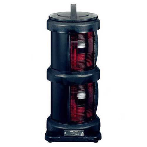
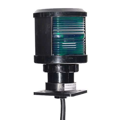
Sidelights (Port and Starboard Lights):
Color: Red (port side) and green (starboard side)
Purpose: Communicate the direction and heading of the vessel, aiding in collision avoidance.
Sternlight:
Color: White
Purpose: Indicates the size and direction of motion of the vessel to those behind it, especially important for passing or trailing vessels.
Masthead Light (Steaming Light):
Color: White
Purpose: Mounted atop the vessel's mast, indicates the presence of a vessel and is visible when the ship is in motion and under power.
Towing Lights:
Colors: Yellow (towing light) above a white masthead light
Purpose: Indicates vessels involved in towing, aiding in collision avoidance.
All-Round Light (360-Degree Light):
Color: White
Purpose: Emits light in all directions, used when a vessel is at anchor or not under command.
Anchor Lights:
Color: White
Purpose: Visible when a vessel is at anchor, helps avoid collisions, and indicates the vessel's position.
Special Purpose Lights:
Purpose: Customized lights for specific vessels, such as fishing or pilot boats, conveying information about their operations to prevent accidents.
Navigation Light Combinations:
Purpose: Vary based on vessel type, purpose, and operations, aiding in determining the vessel's type and nautical status. Governed by COLREGs for global uniformity.
Evolution Technologies for Marine Navigation Lights
Incandescent Bulbs:
Traditional bulbs emitting light when an electric current passes through a filament.
LED (Light-Emitting Diode) Lights:
Energy-efficient, long-lasting, and bright lights revolutionizing marine navigation.
Automated Systems and Sensors:
Controls light intensity based on external factors like ambient light, weather, and vessel movement.
Remote Monitoring and Control:
Allows operators to remotely monitor and control navigation lights through digital interfaces or software.
Improved Durability and Reliability:
Modern materials and sealing techniques enhance durability, protecting lights from water intrusion and corrosion.
Compliance with Regulations:
Built-in compliance functions ensure lights adhere to international norms and standards.
Wireless Communication:
Enables communication between navigation lights and other vessel systems, improving overall safety and coordination.
GPS Integration:
Integrating GPS technology for accurate positioning and displaying appropriate navigation light combinations.
Conclusion:
Marine navigation lights enabling sailors to navigate intricate waterways and reach their destinations safely, from classic sidelights to modern LED systems, symbolize the essence of maritime navigation. Through continuous technological evolution, these lights have become more reliable, energy-efficient, and adaptable, contributing to the enhancement of maritime safety on a global scale.
CNC machining, utilizing advanced CNC machining tools, offers distinct advantages such as stable machining quality, high accuracy, repetition precision, and efficiency. To meet the design accuracy requirements of parts, a systematic approach to CNC machining processes is essential. This article explores the principles and methods for dividing CNC machining processes and arranging their sequences.

How To Divide CNC Machining Processes
Process planning encompasses the entire machining process, requiring careful consideration of factors such as part structure, machine tool capabilities, and CNC machining content. The division of CNC machining processes can be approached through the following methods:
1. Centralized Tool Sorting Method
Divide processes based on the tools used, aiming to utilize the same tool CNC for processing all applicable parts. This minimizes tool changes, reduces idle time, and mitigates positioning errors.
2. Sorting Method of Processing Parts
For parts with extensive CNC processing, divide them based on structural characteristics such as internal shape, outer shape, or specific surfaces. Prioritize processing planes and locating surfaces, followed by holes, simple geometric shapes, and then complex shapes.
3. Rough and Fine Machining Sequence Method
Apply a sequence method for parts prone to deformation, involving separate rough and fine CNC machining. Calibration after rough machining addresses potential deformations, ensuring precision.

Principles For The Sequence Arrangement Of CNC Machining Processes
1. Principle of Rough Before Fine
Sequentially progress through rough machining, semi-finish machining, and finish machining to gradually enhance precision and surface quality. Consider allowing a resting period between rough and finish machining for stress release, particularly beneficial for parts with high accuracy requirements.
2. Principle of Machining Datum Plane First
Initiate machining with the surface designated as the finishing reference, ensuring accuracy and minimizing clamping errors. Follow a sequence based on datum conversion and gradual improvement of machining accuracy.
3. Principle of Face Before Hole
Prioritize processing flat surfaces before holes, especially for parts like boxes and brackets. This approach provides a stable reference for subsequent operations and facilitates accurate hole processing.
4. Principle of Inside Before Outside
For precision sleeves, process the hole before the outer circle, ensuring high coaxiality. This simplifies fixture structures and meets stringent requirements for outer circle and hole alignment.
5. Principle of Reducing Tool Change Times
Arrange machining sequences based on the tool entering the machining position to minimize tool changes and enhance overall efficiency.
In conclusion, adhering to these principles and methods ensures a systematic and efficient approach to CNC machining processes, meeting the design accuracy and quality requirements of machined parts.
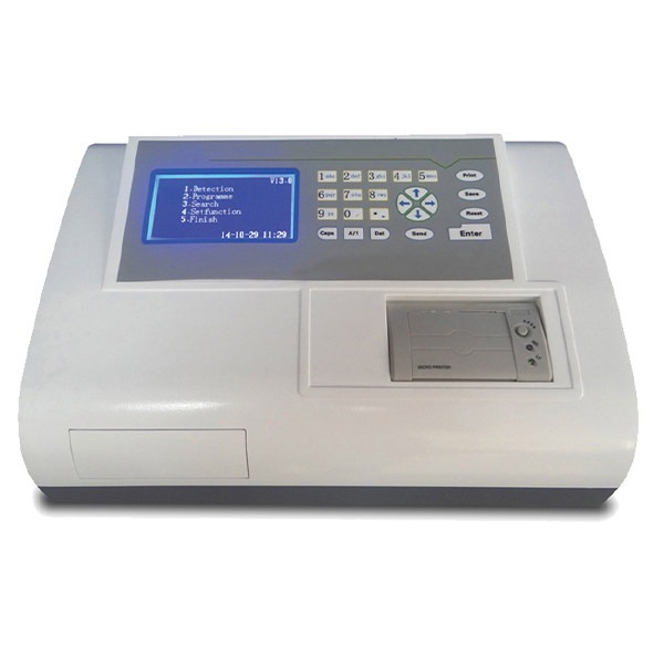
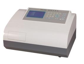
Microplate readers play a crucial role in colorimetric determination, particularly in applications like ELISA. The selection of an appropriate microplate reader involves considering various factors that impact its performance. Here, we explore key considerations in choosing a microplate reader for optimal colorimetric determination.
1. Determination of Wavelength
The determination wavelength of a microplate reader is pivotal for accurate colorimetric assessment. Typically falling between 400 and 750 nm, with an extension up to 800 nm, this range caters to the color determination needs of ELISA. Enzymes like horseradish peroxidase (HRP) and substrates such as tetramethylbenzidine (TMB) contribute to color development. Dual-wavelength colorimetry, involving 450 nm or 492 nm for color development and a less sensitive wavelength like 630 nm, enhances specificity in absorbance readings.
2. Measured Absorbance Range
The absorbance measurement range of a microplate reader is critical, with a general range of 0 to 2.5 covering ELISA requirements. Advancements now allow for ranges exceeding 3.5, ensuring improved precision and linearity in absorbance readings.
3. Detection Speed
The detection speed of a microplate reader directly impacts the precision of colorimetric determination. Faster detection minimizes variations in absorbance among micropores due to different determination times, enhancing overall accuracy.
4. Shake Plate Function
The shake plate function is essential for uniform color distribution in ELISA plate holes before determination. This feature eliminates the need for manual shaking after the color reaction, streamlining the process and ensuring consistency.
5. Incubation Function
Microplate readers offer an incubation function, allowing precise control of internal temperature during ELISA measurements. This feature negates the need for an external thermostat, offering convenience based on laboratory conditions and requirements.
6. Software Function
The software function is a critical aspect, providing statistical analysis and reporting for ELISA qualitative determination. In situations where hardware differences are minimal, software becomes a key indicator of microplate reader quality. Robust software functions greatly assist users in practical work, with features like statistical calculation of positive judgment values, determination of the "cut-off" and "gray area," and curve regression equation calculations enhancing the practical value of the microplate reader.
In conclusion, selecting a microplate reader involves a comprehensive evaluation of factors such as determination wavelength, absorbance range, detection speed, shake plate function, incubation function, and software capabilities. These considerations collectively contribute to the effectiveness and reliability of colorimetric determination in various laboratory applications.