The emergence of smart technology has revolutionized traditional web guide systems, paving the way for the advent of smart web guide systems. These sophisticated systems, driven by artificial intelligence (AI) and automation, mark a groundbreaking shift towards unparalleled accuracy, adaptability, and efficiency in web guiding within modern manufacturing. Let's explore the intricacies of smart web guide systems and their transformative impact on the manufacturing landscape.

Key Techniques of Smart Web Guide Systems:
Harnessing Artificial Intelligence: Smart web guide systems leverage AI to enable robots to learn from data, adapt to changing conditions, and autonomously make decisions. By analyzing real-time sensor data, AI algorithms detect web alignment errors and automatically adjust guide mechanisms, ensuring precise alignment and minimizing waste and downtime.
Adaptive Machine Learning: These systems utilize adaptive machine learning algorithms to continuously improve performance. By studying past data and user feedback, smart web guide systems adjust guide settings to accommodate different materials, speeds, and environmental conditions, optimizing performance with minimal manual intervention.
Predictive Analytics for Proactive Maintenance: Smart web guide systems excel in anticipating and preventing maintenance issues before they arise. By monitoring sensor data and equipment performance parameters, predictive analytics algorithms forecast maintenance needs, enabling operators to take preemptive action and minimize unplanned downtime.
Real-Time Monitoring and Optimization: Providing real-time monitoring of web alignment and tension, smart web guide systems offer operators valuable insights into process performance. With advanced visualization tools and dashboards, operators can monitor system status and make informed decisions while real-time optimization algorithms adjust guide settings for maximum efficiency.
Enhanced Integration and Connectivity: In the era of Industry 4.0, connectivity and integration are paramount. Smart web guide systems seamlessly integrate with existing production equipment and enterprise systems, enabling end-to-end visibility and control to optimize workflow efficiency.
Advanced Control Algorithms: Utilizing advanced control algorithms such as PID controllers and MPC, smart web guide systems ensure precise adjustment of guide mechanisms for optimal performance based on sensor data and feedback mechanisms.
Human-Machine Interface (HMI): Intuitive user interfaces and visualization tools empower operators to effectively monitor and manage web guiding processes, with features including dashboards, alerts, and diagnostic tools.
Energy Efficiency Optimization: Smart web guide systems prioritize energy efficiency through the integration of energy-efficient components and optimization techniques, minimizing energy consumption while maintaining precise web control.
Fault Tolerance and Redundancy: Employing fault-tolerant design principles and redundancy mechanisms, these systems ensure reliability and uptime, with redundant sensors, actuators, and control circuits minimizing the risk of production interruptions.
Remote Monitoring and Diagnostics: Remote accessibility enables operators to monitor and monitor and troubleshoot web guiding systems from any location, facilitating proactive maintenance and optimization of web guiding processes.
Benefits of Smart Web Guide Systems:
Precision and Accuracy: Ensures consistent web alignment and tension control.
Efficiency and Productivity: Minimizes waste, downtime, and manual intervention, enhancing productivity.
Operator Convenience: User-friendly interfaces simplify operation and monitoring.
Adaptability and Flexibility: Responds to changing production requirements in real-time.
Conclusion:
Smart web guide systems represent a significant advancement in web guiding technology, offering unparalleled precision, efficiency, and automation. As smart manufacturing continues to evolve, these systems will play a crucial role in driving innovation and competitiveness across various industries.
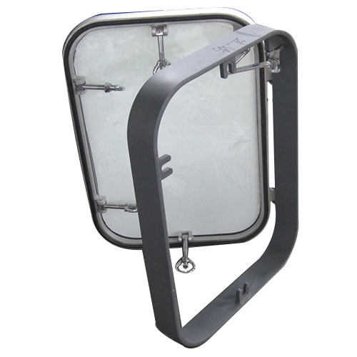
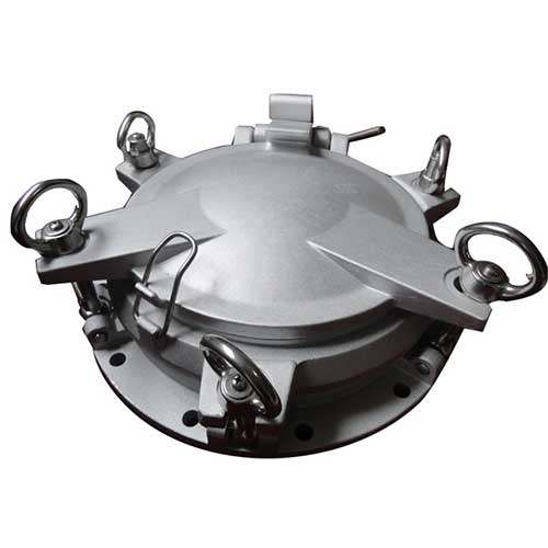
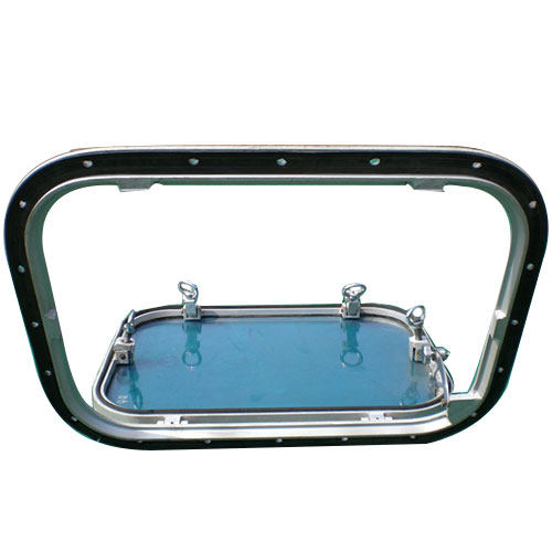
The effects of climate change on marine environments have become increasingly evident, reshaping marine ecosystems and the vital "windows" they provide into the underwater world. From coral reefs to polar seas, these repercussions alter ecosystems in significant ways, emphasizing the crucial role of marine windows in our understanding and preservation of oceanic health.
The Vital Role of Marine Windows in Ecosystems:
Marine windows serve as metaphorical portals into the intricate underwater world, playing a pivotal role in scientific research and serving as indicators of oceanic well-being. These windows, including coral reefs, polar ice caps, and coastal regions, offer insights into the health of marine ecosystems.
Climate Change's Impact on Marine Windows:
1. Coral Reefs: Fragile Ecosystems Under Pressure
Coral reefs, renowned as the rainforests of the sea, support a vast array of marine life. However, climate change-induced stressors threaten their existence:
Temperature Stress: Rising sea temperatures trigger coral bleaching, weakening corals and increasing susceptibility to disease.
Ocean Acidification: Increased carbon dioxide absorption leads to acidification, hindering coral growth and reef formation.
Extreme Weather Events: Intensifying storms cause physical damage to coral reefs, further exacerbating their degradation.
2. Polar Regions: Melting Ice and Shifting Landscapes
Polar regions experience rapid transformations due to global warming:
Loss of Sea Ice: Shrinking Arctic sea ice imperils species reliant on it, such as polar bears and seals.
Thinning Ice Sheets: Warming temperatures in Antarctica contribute to ice shelf thinning and glacier retreat.
Altered Ecosystem Dynamics: Disruptions in ice cover and temperature regimes destabilize polar ecosystems, affecting marine life and food webs.
3. Coastal Zones: Frontlines of Human-Induced Changes
Coastal areas face escalating threats from climate change and human activities:
Sea Level Rise: Coastal flooding and saltwater intrusion endanger communities and ecosystems.
Habitat Loss: Development, pollution, and overfishing degrade critical marine habitats.
Ocean Pollution: Climate change exacerbates ocean pollution, disrupting marine ecosystems and compromising water quality.
Strategies to Mitigate Climate Change's Impact on Marine Windows:
Addressing climate change's impact on marine ecosystems requires a comprehensive approach:
Reduce Greenhouse Gas Emissions:
Transition to renewable energy sources and implement energy efficiency measures.
Foster international cooperation to limit carbon emissions.
Protect and Restore Marine Ecosystems:
Establish marine protected areas and adopt sustainable fisheries management practices.
Support habitat restoration efforts to enhance ecosystem resilience.
Adaptation Strategies for Vulnerable Ecosystems:
Develop tailored adaptation measures for vulnerable ecosystems, such as coral reefs and polar regions.
Invest in research and monitoring to inform adaptive management strategies.
Reduce Coastal Vulnerability:
Implement coastal management strategies and sustainable land-use planning to mitigate coastal erosion.
Promote community-based approaches to climate resilience-building and ocean governance.
Enhance Ocean Governance and International Cooperation:
Strengthen governance frameworks and foster collaboration among stakeholders for sustainable ocean management.
Support initiatives that integrate climate considerations into marine policy and planning processes.
Conclusion:
Climate change poses profound threats to marine ecosystems, as evidenced by the impacts observed through coral reefs, polar seas, and coastal zones. Protecting these critical ecosystems requires concerted efforts to mitigate climate change and adapt to its consequences. By safeguarding marine windows, we safeguard the biodiversity and ecological integrity of our oceans, ensuring a sustainable future for generations to come.
In the realm of analytical chemistry, UV-Vis spectrophotometers play an indispensable role in exploring the interaction between light and matter. These sophisticated instruments empower scientists and researchers to precisely measure the absorption or transmission of light across the ultraviolet (UV) and visible (Vis) regions of the electromagnetic spectrum. Whether you're a novice student conducting experiments in a laboratory or a seasoned scientist analyzing complex samples, proficiency in operating a UV-Vis spectrophotometer is essential for achieving accurate and reliable results. In this comprehensive guide, we will walk you through the essential steps of utilizing a UV-Vis spectrophotometer, enabling you to confidently navigate the intricacies of light-matter interactions and unlock invaluable insights in your research endeavors.

A General Guide on Using a UV-Vis Spectrophotometer:
1. Familiarize Yourself with the Instrument:
Begin by thoroughly reviewing the user manual provided by the UV-Vis spectrophotometer manufacturer to gain insight into the specific features and functionalities of your UV-Vis spectrophotometer.
Verify that the instrument is in optimal working condition by conducting routine checks and maintenance procedures as outlined in the manual.
2. Prepare Your Sample:
Depending on the nature of your analysis, prepare a sample suitable for UV-Vis measurements. This may entail dilution, filtration to remove particulate matter, or other necessary preparatory steps.
3. Set Up the Instrument:
Ensure proper connection of the spectrophotometer to a stable power source and switch it on. Allow the instrument to warm up if required, adhering to the manufacturer's instructions.
Configure the instrument settings, including wavelength range and other parameters specific to your analysis requirements.
4. Perform a Blank Measurement:
Prior to measuring your sample, conduct a blank measurement to establish a baseline absorbance. This involves measuring the absorbance of the solvent or reagent used in your sample, without any analyte present, to serve as a reference point for subsequent measurements.
5. Calibration (if Necessary):
Depending on the analytical requirements, Perform calibration using appropriate standards to ensure precise and accurate measurements of the spectrophotometer, particularly for quantitative analyses.
6. Measure Your Sample:
Place the prepared sample into a clean and flawless cuvette, designed for containing liquid samples. Ensure the cuvette is devoid of scratches or defects that may affect measurement accuracy. Insert the cuvette into the sample compartment of the spectrophotometer.

7. Select the Desired Wavelength:
Set the spectrophotometer to the desired wavelength for your measurement, either manually or through the instrument's control panel or software interface.
8. Initiate Absorbance Measurement:
Commence the measurement process, during which the spectrophotometer emits light at the selected wavelength through the sample. The instrument quantifies the amount of light absorbed by the sample, represented as absorbance (A).
9. Record the Data:
Record the absorbance value obtained from the spectrophotometer for your sample. If conducting measurements across multiple wavelengths, systematically record the data for further analysis.
10. Analyze and Interpret the Data:
Utilize suitable mathematical or statistical methods to analyze the acquired data, correlating absorbance values with the concentration or other relevant parameters of your sample.
Compare results with calibration curves or reference data to derive meaningful interpretations and conclusions from your analysis.
11. Clean Up:
Following completion of measurements, meticulously clean the cuvettes to eliminate any residual sample material. Adhere to proper disposal procedures for any generated waste or chemicals.
Conclusion:
Proficiency in utilizing a UV-Vis spectrophotometer unlocks myriad applications across diverse fields such as pharmaceuticals, environmental analysis, and material science. By adhering to the step-by-step instructions outlined in this guide, you can confidently conduct measurements, analyze your data, and derive meaningful insights. Remember to consult the manufacturer's user manual for specific details regarding your instrument's functionality and features. With practice and a deeper understanding of UV-Vis spectrophotometry principles, you will harness the full potential of this powerful analytical tool, driving scientific progress and contributing to impactful discoveries in your respective disciplines.
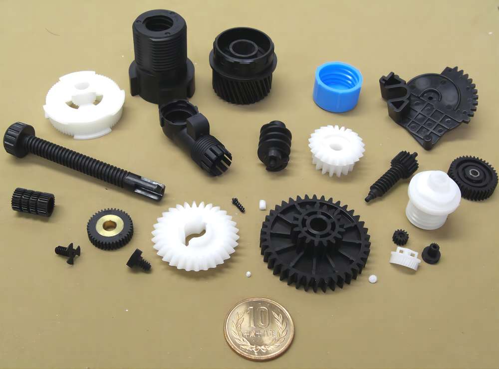
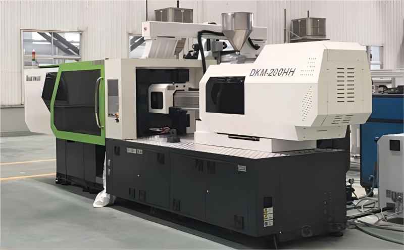
Injection molding manufacturing process involves injecting molten plastic into a mold cavity to produce intricate and precise parts. Renowned for its capacity for high production rates, excellent repeatability, and ability to manufacture parts with complex geometries, injection molding offers numerous advantages. However, achieving optimal results requires careful consideration of various factors, including cycle time, shrinkage, and troubleshooting common issues that may arise during production.
Understanding Cycle Time:
Cycle time in injection molding refers to the duration required to complete one injection molding cycle, encompassing the injection of plastic material into the mold, cooling, and ejection of the finished part. This crucial parameter is influenced by several factors:
Part Complexity: Parts with intricate geometries or complex features may necessitate longer cycle times to ensure proper filling and cooling.
Material Type: Different plastic materials have distinct flow properties and cooling characteristics, impacting cycle times.
Mold Design: The mold's design and configuration, including the number of cavities and gating system, affect cycle time.
Machine Capability: The injection molding machine's specifications, such as injection speed and cooling capacity, influence cycle times.
Determining cycle time involves optimizing the injection molding process by adjusting parameters like temperature, pressure, and flow rate. Trial runs are typically conducted to identify the most efficient settings for achieving the desired cycle time while maintaining part quality.
Calculating Shrinkage Factor:
Shrinkage is the dimensional change that occurs in a part as it cools and solidifies after injection molding. Calculating the shrinkage factor is crucial for designing molds and predicting the final dimensions of the molded part. The process involves:
Measuring Part Dimensions: Measure the dimensions of the finished part using precision tools.
Determining Mold Dimensions: Measure the dimensions of the mold cavity.
Subtracting Dimensions: Calculate the difference between the part dimensions and the mold dimensions to determine shrinkage.
Calculating Shrinkage Factor: Divide the shrinkage by the original dimension to obtain the shrinkage factor.
Performing trials with different materials and processing conditions is essential to accurately determine the shrinkage factor for specific parts.
Troubleshooting Common Issues:
Injection molding may encounter various challenges during production, including warping, sinking, short shots, flashing, and jetting. Addressing these issues requires a systematic approach:
Identify Root Causes: Determine the underlying factors contributing to the problem, such as mold design, material properties, or processing parameters.
Adjust Parameters: Modify injection speed, pressure, temperature, or cooling time to optimize process conditions.
Enhance Mold Design: Improve mold venting, gate design, or part geometry to alleviate issues like flashing or short shots.
Implement Quality Control: Regularly monitor process parameters and inspect parts for defects to detect and address issues promptly.
By understanding these key aspects of injection molding and implementing effective strategies, manufacturers can produce high-quality parts that meet specifications, maximize efficiency, and minimize production costs. Consistent monitoring, analysis, and optimization of the injection molding process are essential for achieving success in this versatile manufacturing method.
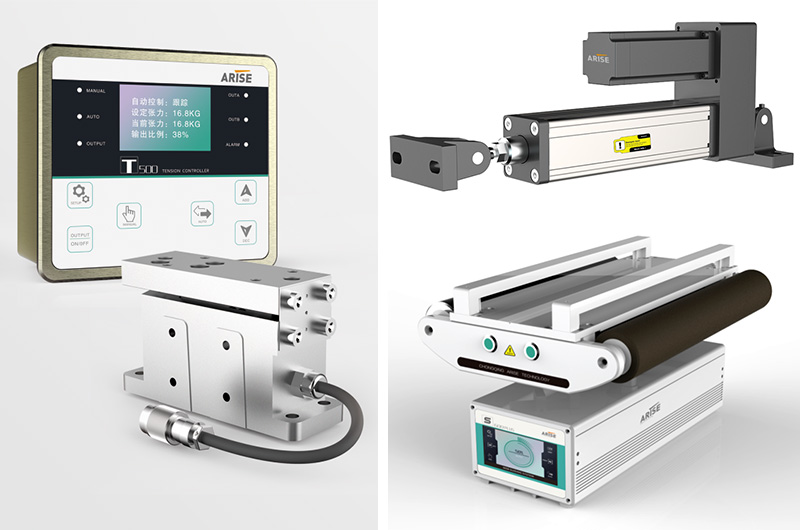
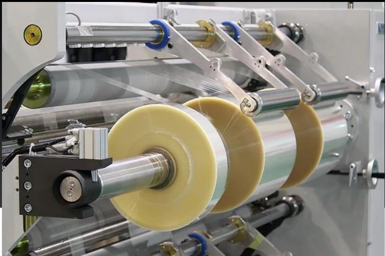
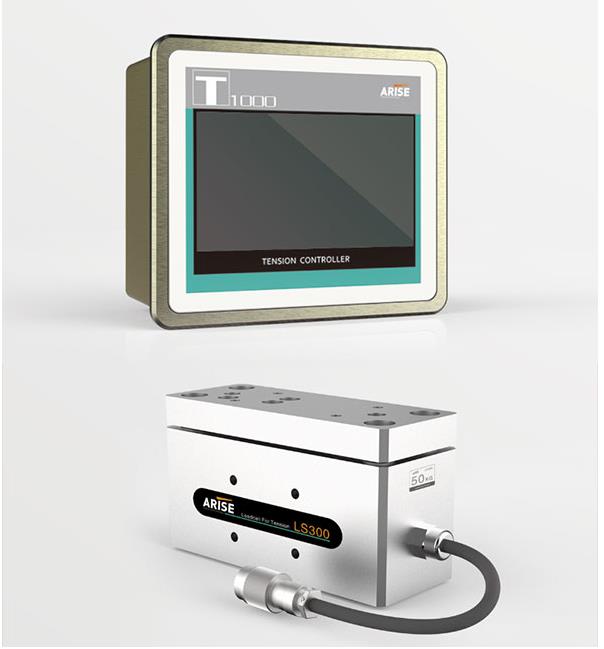
Optimizing energy consumption stands as a cornerstone for sustainability and cost-effectiveness across various manufacturing operations. Among these, tension control emerges as a critical factor in industries such as web handling, printing, packaging, and textiles. Exact tension levels are pivotal for product quality and operational efficiency. Yet, traditional tension control mechanisms often incur significant energy costs. To address this challenge, industries are increasingly adopting energy-efficient tension control solutions.
Benefits of Energy-Efficient Tension Control Solutions:
Cost Savings:
Energy-efficient tension control solutions drastically reduce energy consumption, leading to lower utility bills and operating costs. Businesses can enhance their bottom line by optimizing energy usage and utilizing resources more efficiently.
Environmental Sustainability:
Energy efficiency directly contributes to environmental sustainability by reducing carbon footprint. Lower energy consumption helps mitigate climate change, showcasing a commitment to environmental responsibility and corporate citizenship.
Compliance with Regulations:
Many regions impose strict regulations regarding energy usage and environmental impact. Adopting energy-efficient technologies ensures compliance with these regulations, averting potential penalties or fines. Moreover, it enhances brand reputation and market competitiveness by demonstrating adherence to sustainability initiatives.
Enhanced Equipment Performance:
Energy-efficient tension control solutions integrate advanced technologies and intelligent algorithms to optimize system performance. By maintaining precise tension levels and minimizing energy waste, these solutions enhance equipment reliability, longevity, and overall operational efficiency.
Improved Product Quality:
Precise tension control is paramount for product quality and integrity, particularly in industries like printing, packaging, and textiles. Energy-efficient tension control solutions ensure uniform tension levels, reducing the risk of product defects, waste, and rework, thereby enhancing customer satisfaction and brand reputation.
Flexibility and Adaptability:Energy-efficient tension control solutions are designed to be versatile and adaptable to varying production requirements and process conditions. They offer flexibility and customization options to meet specific operational needs, whether adjusting tension levels for different materials, speeds, or environmental factors.
Future-Proofing Investments:
Investing in energy-efficient solutions not only yields immediate cost savings but also shields businesses from escalating energy bills and evolving regulatory requirements. Prioritizing energy efficiency secures the durability and sustainability of operations amid changing market circumstances.
Innovative Approaches in Energy-Efficient Tension Control Solutions:
Regenerative Braking Systems:
Regenerative braking systems capture and store excess kinetic energy generated during braking for later utilization. By converting this energy into electrical energy, these systems reduce energy consumption and manage peak power demands efficiently.
Intelligent Control Algorithms:
Intelligent tension control algorithms monitor and adjust tension levels in real-time based on variables like material type, speed, and environmental conditions. These algorithms optimize tension control parameters, minimizing energy waste while maintaining optimal tension levels.
Low-Friction Components:
Utilizing low-friction materials, coatings, and design optimizations within tension control components reduces frictional losses and energy requirements. This minimizes resistance and enhances material movement smoothness, contributing to energy efficiency and equipment lifespan extension.
Variable Frequency Drives (VFDs):
VFDs enable precise adjustment of motor speeds based on process requirements, resulting in energy savings. By matching motor speed to required tension levels, VFDs eliminate energy wastage associated with constant-speed operation and reduce mechanical stress on equipment.
Predictive Maintenance and Condition Monitoring:
Predictive maintenance techniques and condition monitoring systems identify potential issues before they escalate into costly failures. Regular monitoring and analysis of tension control equipment condition optimize system efficiency, preventing energy losses due to unexpected downtime or malfunctions.
System Integration and Optimization:
Integrating tension controllers with broader energy management platforms enables comprehensive optimization of energy usage across manufacturing processes. This holistic approach synchronizes tension control operations with other energy-intensive equipment and processes, maximizing energy efficiency and overall productivity.
Conclusion:
Energy-efficient tension control solutions offer enterprises an opportunity to enhance operations while reducing environmental impact. By leveraging innovative technology, intelligent algorithms, and integrated energy management systems, businesses can achieve significant energy savings, improving productivity and sustainability simultaneously.