In today's fast-paced production environments, precision and quality are paramount. The integration of print inspection capabilities into web inspection systems emerges as a transformative advancement, revolutionizing quality assurance practices across industries from packaging to printing. This convergence of technologies empowers manufacturers with unprecedented accuracy and efficiency, ensuring the delivery of flawless products to consumers.

Evolution of Integrated Systems:
Manufacturers, driven by the demand for perfection in printed goods, have expanded the capabilities of web inspection systems by integrating print inspection functionality. This collaborative approach enables not only the assessment of material integrity but also the scrutiny of printed content's accuracy and quality.
Key Features of Integrated Systems:
Comprehensive Inspection:
Integrated systems offer complete inspection capabilities, allowing simultaneous examination of both material surface and printed content. This holistic approach ensures the detection of printing issues, such as misprints, color disparities, and registration irregularities, alongside physical defects in the material.
Real-time Detection:
Leveraging advanced imaging technology and intelligent algorithms, integrated systems enable real-time detection of printing flaws as materials traverse the web inspection setup. This proactive approach empowers manufacturers to promptly identify and rectify defects, minimizing the production of subpar or non-compliant products.
Multi-parameter Inspection:
Integrated systems can scrutinize multiple parameters of printed content, including text, graphics, barcodes, and color fidelity. This comprehensive assessment ensures adherence to design specifications and regulatory standards, guaranteeing superior quality in the final product.
Adaptability:
Highly adaptable to diverse printing processes and materials, integrated web inspection systems accommodate variations in substrates, inks, and printing methods. Their flexibility allows for customization to meet specific industry requirements and application needs, ensuring versatility in quality assurance practices.
Data Analytics:
Integrated systems generate valuable data insights, capturing information on defect rates, production trends, and performance metrics. This data-driven approach facilitates root cause analysis, process optimization, and continuous improvement initiatives, driving operational excellence.
Benefits of Integration:
Improved Quality Control:
By amalgamating web and print inspection capabilities, manufacturers ensure the highest levels of quality and accuracy in printed goods. Detection and correction of defects in material integrity and printing result in products that meet stringent quality standards and exceed customer expectations.
Reduced Waste and Rework:
Real-time defect detection minimizes the production of flawed or non-compliant items, reducing waste and the need for costly rework. Early intervention and corrective measures prevent defective products from progressing further in the production pipeline, optimizing resource utilization.
Enhanced Efficiency:
Integrated inspection systems streamline quality assurance processes, reducing inspection times and manual intervention. This enhances production efficiency, shortens cycle times, and boosts throughput, leading to significant cost savings and operational enhancements.
Compliance Assurance:
Integrated printing quality inspection systems ensure compliance with regulatory requirements and industry standards by validating the quality and legibility of printed text. This is particularly critical in regulated sectors such as pharmaceuticals and food packaging, where precise adherence to regulations is imperative.
Increased Customer Satisfaction:
By consistently delivering products of superior quality and accuracy, manufacturers enhance customer satisfaction and foster brand loyalty. Integrated inspection systems uphold brand integrity, mitigate the risk of recalls or returns, and elevate the overall customer experience.
Industrial Applications:
The integration of print inspection capabilities into web inspection systems finds diverse applications across industries, transforming quality control and production processes. From packaging to printing, the technology revolutionizes defect detection, ensuring precision and reliability in manufacturing operations.
Future Innovations:
As technology advances, further innovations in print inspection integrated with web inspection systems are anticipated. Enhanced imaging resolution, artificial intelligence algorithms, and machine learning techniques will enable more precise flaw detection, increased accuracy, and greater adaptability to evolving production needs.
In conclusion, the integration of print inspection capabilities into web inspection systems marks a significant milestone in manufacturing quality assurance. By harnessing the strengths of both technologies, manufacturers can achieve unparalleled levels of defect detection, print accuracy, and production optimization, setting new standards of excellence in the industry.
Density, a fundamental physical property, holds significant importance across various industries and scientific domains. Density meters, specialized instruments designed to measure the density of liquids and solids, employ diverse measurement techniques grounded in established scientific principles. This article provides insights into the operational principles of density meters, elucidating how they facilitate precise density measurements.

Working Principle of a Density Meter:
The operating principle of a density meter hinges on Archimedes' principle of buoyancy. Here's a stepwise breakdown of how density meters operate:
Buoyancy Measurement:
The sample under examination is placed within a measurement chamber equipped with a transducer or sensor to gauge the buoyant force exerted on the object.
Reference Measurement:
Prior to analyzing the sample, the density meter undergoes calibration using a known density reference material to ensure measurement accuracy.
Sample Introduction:
The sample is introduced into the measurement chamber, which may accommodate either liquid or solid samples, often with provisions for temperature regulation to ensure consistent readings.
Buoyant Force Measurement:
Upon immersion in a fluid, the sample experiences an upward force termed buoyant force, arising from its displacement of the fluid.
Sensor Detection:
The density meter's transducer or sensor detects the buoyant force exerted on the sample, typically converting this measurement into an electrical signal for processing.
Density Calculation:
Leveraging calibration data derived from the reference material, the density meter computes the sample's density based on the measured buoyant force.
Display and Output:
The estimated density value is displayed on the density meter's screen or transmitted to an external device for further analysis. Some density meters offer additional features like temperature compensation or specific gravity calculation.
It's important to note that different types of density meters may employ varying operating principles and measurement procedures. Nonetheless, the underlying principle of measuring buoyant force remains consistent across these instruments.

Working Mechanism of Density Meters:
Oscillation-Based Density Meters:
Oscillation-based density meters, including oscillating U-tube and vibrating tube density meters, utilize oscillation frequency to determine density.
Oscillation Initiation: The density meter initiates oscillation or vibration within a chamber or tube, often facilitated by a piezoelectric or vibrating device.
Frequency Measurement: Sensors or transducers in the density meter measure the resonant frequency of the oscillation, which is influenced by the sample's bulk and density.
Comparison with Reference: The measured resonant frequency is compared to a known reference frequency associated with a predetermined density value.
Density Calculation: Based on the frequency difference between the measured and reference frequencies, the density meter calculates the sample's density using calibration data.
Vibrating Element-Based Density Meters:
Vibrating element-based density meters, such as tuning fork density meters, exploit the damping effect on a vibrating element immersed in a fluid to ascertain density.
Vibrating Element: The density meter sets a vibrating element, such as a quartz crystal or tuning fork, into motion at a specific frequency.
Damping Effect: Immersion of the vibrating element in the sample fluid induces a damping effect influenced by the fluid's density.
Frequency Shift Measurement: Sensors or transducers detect the frequency shift in the vibrating element induced by the damping effect.
Calibration and Conversion: The density meter is calibrated using known density reference standards to establish a correlation between frequency shift and density, enabling conversion of the former into a corresponding density value.
Summary:
Density meters serve as invaluable tools for estimating the density of liquids and solids, contributing to quality control, process optimization, and research endeavors. By leveraging established principles like Archimedes' law and innovative measurement techniques, density meters offer accurate and reliable density readings, facilitating breakthroughs across various domains.
Galvanized bolts are widely used for their rust and corrosion-resistant properties, achieved through zinc coating. However, despite this protection, galvanized bolts can still rust under certain conditions. This article delves into the factors contributing to the rusting of galvanized bolts and provides solutions to mitigate these issues.
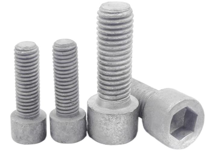
What are Galvanized Bolts?
Galvanized bolts are steel bolts coated with zinc to form a protective layer against rust and corrosion. The zinc coating acts as a sacrificial barrier, corroding before the underlying steel, thus shielding it from environmental elements like moisture and oxygen.
Factors Causing Rusting of Galvanized Bolts:
Damage to the Zinc Coating:
Damage to the zinc coating, such as scratches or chips, exposes the steel to moisture and oxygen, facilitating rust formation. Mishandling during installation, shipping, or storage, along with contact with abrasive surfaces, can compromise the integrity of the zinc coating.
Solution: Handle galvanized bolts with care, avoiding impacts and storing them in dry, well-ventilated areas away from corrosive substances. Repair or replace bolts with damaged coatings promptly.
Exposure to Harsh Environments:
Prolonged exposure to corrosive environments, such as marine or industrial settings, accelerates zinc coating breakdown. High salt content in seawater or pollutants in industrial areas can dissolve zinc coatings, leaving the steel vulnerable to rust.
Solution: Select galvanized coatings tailored to specific environments and conduct regular inspections for damage. Implement maintenance measures like cleaning or recoating to prevent rust formation.
Dissimilar Metal Contact:
When hot dip galvanized bolts come into contact with dissimilar metals, it can induce electrochemical reactions that degrade the zinc coating. This occurs due to variations in electrode potentials between metals.
Solution: Use insulating materials to prevent direct contact between galvanized bolts and dissimilar metals, minimizing galvanic corrosion.

Improper Installation:
Incorrect installation practices, such as overtightening bolts or trapping moisture between mating surfaces, can damage zinc coatings and create conditions conducive to rusting.
Solution: Follow manufacturer's installation guidelines and torque specifications, avoiding over-tightening. Ensure mating surfaces are clean and dry before installation.
Chloride Contamination:
Chloride pollutants, found in saltwater and deicing salts, accelerate zinc coating corrosion. Chloride ions penetrate the zinc layer, reaching the steel surface and initiating rust formation.
Solution: Use galvanized bolts with thicker zinc coatings or additional protective coatings designed for chloride-rich environments. Regular maintenance and inspection are essential to detect and address corrosion promptly.
Summary:
While galvanized bolts offer corrosion resistance, various factors can lead to rusting. Awareness of these conditions and implementing preventive measures are crucial for maintaining the integrity and longevity of galvanized bolt installations.
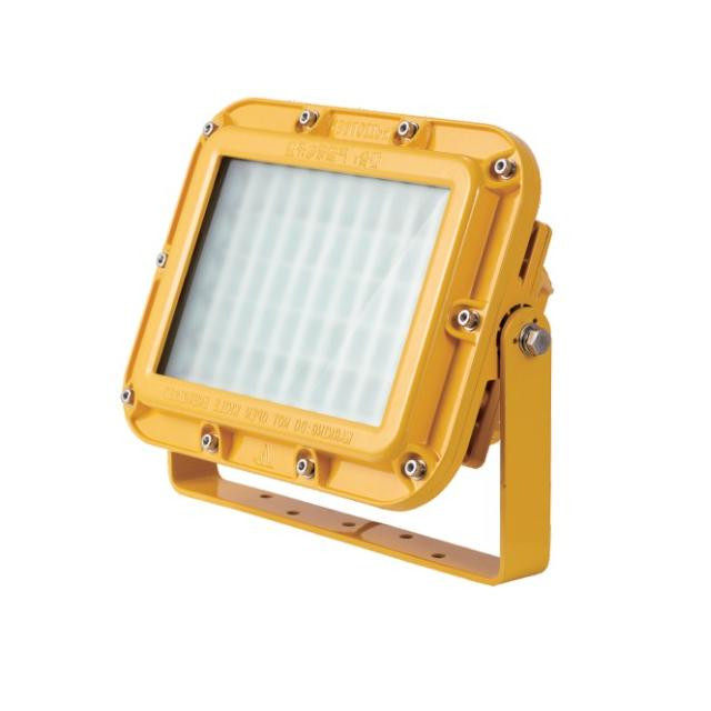
Emergency and safety lighting systems are vital for ensuring the safety and security of marine vessels, their crew, and passengers. These systems serve multiple purposes, including navigation, emergency preparedness, distress signaling, operational safety, and compliance with regulations. This article explores the importance, components, and technological advancements in emergency and safety marine lighting systems.

Importance of Emergency and Safety Marine Lighting Systems:
Navigational Aid:
Marine LED Navigation Lights guide vessels through dark waters and adverse weather conditions, minimizing the risk of collisions by communicating a vessel's position, direction, and status to others.
Emergency Preparedness:
Essential for readiness during emergencies, these lighting systems provide immediate illumination to guide crew and passengers to safety, ensuring swift and orderly evacuation procedures.
Distress Signaling:
Safety lighting systems include signaling devices like strobe lights and distress flares to attract attention and summon assistance in critical situations.
Operational Safety:
Floodlights and spotlights enhance operational safety by illuminating obstacles, hazards, or other vessels, aiding in navigation, docking, and search and rescue operations.
Compliance with Regulations:
International maritime regulations mandate the installation and maintenance of emergency and safety lighting systems on all marine vessels to ensure uniform safety standards.
Components of Emergency and Safety Marine Lighting Systems:
Navigation Lights:
Including red port lights, green starboard lights, white stern lights, and white masthead lights, these lights indicate a vessel's position and direction to others.
Emergency Lighting:
Consisting of emergency exit lights, emergency illumination, and battery backup systems, these lights facilitate safe evacuation during emergencies.
Signal Lights:
Strobe lights, beacon lights, and distress flares are used for distress signaling and communication with other vessels or search and rescue teams.
Floodlights and Spotlights:
Floodlights provide general illumination, while spotlights offer focused illumination for specific areas or objects.
Remote-Controlled Lights:
Remote-controlled floodlights and spotlights allow operators to adjust lighting parameters for optimal visibility.
Backup Power Systems:
Emergency generators and battery banks ensure uninterrupted operation of critical lighting components during power outages.
Technological Advancements in Emergency and Safety Marine Lighting Systems:
LED Technology:
LEDs offer energy efficiency, longevity, durability, and instantaneous operation compared to traditional lighting sources.
Smart Lighting Controls:
Advanced lighting control systems optimize energy usage, enable remote monitoring, and dynamically adjust lighting parameters.
Wireless Connectivity:
Wi-Fi or Bluetooth connectivity facilitates centralized control and remote access of lighting systems, enhancing flexibility and responsiveness.
Integrated Light and Sound Signals:
Integration of visual and auditory signals enhances emergency notifications, ensuring prompt response and evacuation.
Compliance with Regulatory Standards:
Manufacturers adhere to stringent regulatory standards to ensure the highest safety and performance requirements are met.
Conclusion:
Advancements in emergency and safety marine lighting systems have transformed maritime safety, offering enhanced reliability, efficiency, and functionality. These systems play a critical role in ensuring safe and efficient maritime operations, providing illumination, navigation aids, and distress signals for vessels and their occupants. With continuous technological innovation, modern marine lighting systems uphold the highest safety standards.
In the dynamic realm of oil and gas drilling, ensuring the stability and safety of a well stands as a critical priority. When unforeseen circumstances arise, such as kicks or blowouts, well control methods like the Driller's Method become indispensable in regaining control over the well. This article offers a thorough examination of the Driller's Method in Well Control, exploring its mechanics, historical context, and the crucial role of well control training simulations in mastering this essential technique.

Understanding the Basics of the Driller's Method in Well Control:
1. Basics of Well Control: Before delving into the specifics of the Driller's Method, it's essential to grasp the broader concept of well control. Well control encompasses various techniques and strategies aimed at managing and regulating pressure within the wellbore. This meticulous pressure control is not just a matter of operational convenience but a fundamental aspect ensuring safety and environmental protection in drilling operations.
2. Key Techniques Used in the Driller's Method:
Recognition and Well Closure: The process begins with identifying irregular pressure conditions within the well, often triggered by an influx like a gas or oil kick. Prompt action is then taken to shut down the well by activating the blowout preventer (BOP) and halting drilling operations to prevent further influx of fluids or hydrocarbons.
Pressure Assessment: A detailed assessment of downhole conditions follows, evaluating both pressure and volume associated with the kick. Accurate measurements lay the groundwork for effective implementation of the Driller's Method.
First Circulation: With the well shut in, the drilling team initiates the first circulation. Heavy drilling mud, typically weighted with barite, is pumped down the drill string and into the well to gradually increase mud density and balance formation pressure, halting the influx.
Pressure Monitoring: Continuous monitoring of pressure at the wellhead occurs during the first circulation. Observing pressure response helps the drilling team gauge the effectiveness of introducing heavy mud.
Second Circulation: Once pressure stabilizes to match desired bottom hole pressure (BHP), the first circulation concludes. The drilling team then proceeds with the second circulation, circulating drilling mud out of the well to replace the lighter mud or influx introduced during the kick.
The Importance of the Driller's Method:
The Driller's Method holds significance as a pivotal well control approach due to its focus on maintaining constant BHP. This technique not only helps regain control over a well but also minimizes the risk of wellbore instability, additional complications, and potential equipment damage. Through the use of heavy drilling mud and a systematic approach, drilling professionals effectively manage unexpected kicks or blowouts, ensuring personnel safety and environmental protection.
Benefits of the Driller's Method:
Safety: Prioritizes safety by promptly addressing well control incidents, minimizing the risk of uncontrolled flow and potential blowouts.
Equipment Protection: Prevents damage to drilling equipment caused by excessive pressure and flow rates during well control incidents.
Environmental Preservation: Averts environmental disasters by preventing uncontrolled oil or gas releases that could lead to pollution and ecological damage.
Operational Efficiency: Allows drilling operations to resume swiftly and efficiently after a well control incident, minimizing downtime and financial losses.
Role of Well Control Training Simulations for the Driller's Method:
Well control training plays a crucial role in preparing drilling personnel to effectively implement techniques like the Driller's Method. Simulation-based training offers a safe and immersive learning environment, allowing drilling crews to practice and refine their skills in responding to well control incidents.

Simulation in Well Control Training:
Realistic Scenarios: Well control simulators recreate well control incidents accurately, providing trainees with realistic experiences.
Safe Learning Environment: Allows personnel to practice well control techniques without the risks associated with live drilling operations.
Scenario Customization: Simulations can be tailored to mimic specific drilling conditions, enabling personnel to train for their work environment.
Repeatable Training: Trainees can repeat scenarios to build proficiency and confidence in responding to well control incidents.
Feedback and Assessment: Provides immediate feedback on trainees' actions and decisions, facilitating continuous improvement.
Crew Coordination: Facilitates team training, helping drilling crews work together effectively in high-pressure situations.
Conclusion:
Safety and precision are paramount in oil and gas drilling, making techniques like the Driller's Method indispensable. By prioritizing safety, protecting equipment, and preserving the environment, the Driller's Method ensures responsible drilling practices. Well control training simulations play a vital role in preparing drilling personnel for well control incidents, contributing to safer and more efficient drilling operations in the ever-evolving industry.