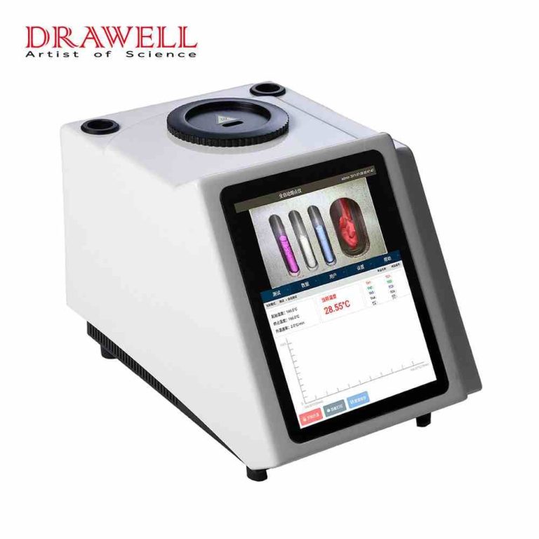
The drug melting point apparatus is a game-changer in pharmaceutical research, seamlessly integrating cutting-edge temperature control and high-definition video camera technology. This innovative combination not only delivers precise, stable, and dependable test results but also offers users an exceptionally convenient testing experience. With high-definition video capabilities, users can effortlessly observe the entire sample melting process, facilitating accurate measurement of melting points and distances.
At its core, the drug melting point apparatus leverages capillary tubes specified in the Pharmacopoeia as sample tubes and utilizes the liquid temperature transfer method, controlled by a computer-driven system for precise temperature management. Its operation is marked by reliability, high-precision temperature control, accurate measurements, excellent reproducibility, and user-friendly operation, all in strict adherence to the instrument, utensil, and determination method standards for melting point determination.
Diagnosing Common Issues and Remedies for Drug Melting Point Apparatus
Absence of Readings in the Final Melting Temperature Display Window
Issue Description: The temperature continues to rise, but the ammeter fails to reach the full scale, rendering the attainment of the final fusion temperature impossible.Analysis: This problem might arise due to the misplacement of the brass tube, blocking the light path, or issues with the light source, such as a broken bulb, incorrect light path alignment, light scattering, or inadequate light energy.
Solution: Adjust the light path to correct the issue.
Ammeter Fails to Reset to Zero After Capillary Insertion
After the drug melting point apparatus is inserted into the capillary, the ammeter should read zero due to the obstruction caused by the medicine in the capillary. When the medicine melts, light passes through the glass capillary, reaching the photocell. The photosensitive output current of the photocell leads to the final melting display and resets the ammeter from zero to full scale. If the ammeter does not reset to zero when the capillary is initially inserted, the device becomes unusable.
Potential Causes for Ammeter Not Resetting to Zero:
Foreign objects in the brass tube where the capillary is placed; remove foreign matter using a thin copper wire, typically caused by broken glass capillaries.
Inadequate resistance; adjust the zero setting using the knob.
Abnormal Temperature Increase After Initial Temperature Setting
Various factors can lead to abnormal temperature fluctuations after pressing the initial temperature setting button, including issues with the temperature sensing element, digital wheel for setting initial temperature, and circuit board components.
Blown Fuse
A blown fuse signifies excessive current flow, often the result of a circuit short-circuit. To rectify this, ensure the load resistance is normal, confirm there are no short circuits in the filter capacitor, and, if required, replace the rectifier diode of the heating circuit power supply with a component of identical parameters.
Anomalies in Measured Values
Anomalies in measured values can be addressed through calibration with standard samples and repeated adjustments. Often, this discrepancy arises when users employ a new capillary from a different batch.
Heating Table Fails to Heat
A non-heating heating table may result from a blown heating wire, fuse, or damaged SCR (Silicon Controlled Rectifier). In the event of a blown heating wire, it can be repaired by rewinding the wire with a 0.3 mm diameter nickel-chromium wire, inserting a 0.5 mm-thick mica paper in between. Alternatively, an electric iron core's heating wire and insulating mica paper can be used. When the SCR is damaged, it must be replaced as it controls the heating current's magnitude by varying the conduction angle.
In conclusion, through understanding advanced technology and thorough troubleshooting guidance of the melting point apparatus, enhance the accuracy and efficiency of drug melting point analysis, further advancing pharmaceutical research and development.
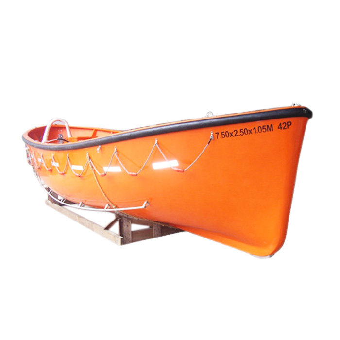
Lifeboats are indispensable vessels created with a singular mission – to rescue and protect lives in emergency situations at sea. Whether it's a shipwreck, a maritime catastrophe, or a search-and-rescue operation, these uncelebrated marine heroes have saved innumerable lives. In this article, we will delve into the pivotal role that lifeboats play in maritime safety, examining their construction materials, design, and features.
Commonly Used Construction Materials for Lifeboats:
Lifeboats are constructed using materials carefully chosen for their durability, buoyancy, and resistance to the harsh conditions of the sea. Common materials used in lifeboat construction include:
Fiberglass: Fiberglass-reinforced composite materials are popular for lifeboat construction due to their lightweight nature, high strength-to-weight ratio, and corrosion resistance. Fiberglass lifeboats are renowned for their resilience and ability to withstand challenging marine environments.
Aluminum: Aluminum lifeboats are favored for their lightweight yet robust construction. They exhibit high resistance to corrosion, making them ideal for use in saltwater environments. Aluminum lifeboats are commonly employed on offshore facilities and smaller vessels.
Steel: Steel lifeboats are noted for their ruggedness and durability. They are capable of handling heavy-duty applications and are frequently used on larger vessels and cargo ships. Steel lifeboats are less susceptible to damage from accidents or severe seas.
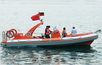
Inflatable Materials: Some lifeboats are designed as rigid inflatable boats (RIBs) or inflatable life rafts. These typically feature an inflatable buoyancy tube and a rigid, lightweight structure made from materials like fiberglass or aluminum. Inflatable lifeboats are celebrated for their buoyancy and stability.
GRP (Glass Reinforced Plastic): GRP lifeboats are lightweight and durable. They exhibit resistance to corrosion and offer good buoyancy. GRP is often used for smaller lifeboats or rescue boats.
Wood: Traditional wooden lifeboats, owing to their vulnerability to rot and deterioration in harsh marine conditions, have been largely replaced by more modern materials. However, some older vessels may still retain wooden lifeboats.
Polyethylene: HDPE (High-Density Polyethylene) is occasionally employed in the construction of smaller lifeboats and life rafts. HDPE is known for its durability and resistance to impact and chemicals.
Design and Features of Lifeboats:
Lifeboats are meticulously designed to ensure maximum safety and efficiency. Key design elements and features include:
Buoyancy and Stability: Lifeboats are engineered to remain buoyant and stable, even in challenging conditions. They must navigate rough seas while keeping occupants safe.
Self-Righting Capability: Many lifeboats are equipped with self-righting mechanisms that automatically return them to an upright position if capsized.
Capacity: Lifeboats come in various sizes and are designed to accommodate a specific number of passengers, often in adherence to international maritime regulations.
Safety Equipment: Lifeboats are typically equipped with essential safety gear, including life jackets, lifebuoys, flares, and communication devices, ensuring the well-being of those on board.
Visibility and Signaling: They are outfitted with bright, reflective colors and lighting to enhance visibility at sea, especially in adverse weather conditions.

The Importance of Lifeboats in Maritime Safety:
Rescue Operations: Lifeboats serve as the first responders in maritime emergencies, providing safe evacuation and rescuing passengers and crew from sinking ships.
Search and Rescue: They are frequently deployed in search-and-rescue missions to locate and recover individuals who have gone missing at sea.
Providing Shelter: In the event of shipwrecks or maritime disasters, lifeboats offer temporary shelter, protecting occupants from inclement weather and sea conditions.
Safety Training: Regular lifeboat drills and training are conducted on ships to prepare crew members and passengers for emergency situations.
Humanitarian Missions: Beyond their primary role, lifeboats have been instrumental in humanitarian efforts, aiding in the rescue of refugees and victims of natural disasters at sea.
Conclusion:
In times of marine peril, lifeboats stand as beacons of hope, a testament to human ingenuity and compassion. Their design and capabilities have evolved over time to meet the increasingly complex demands of modern seafaring. Lifeboats save lives and play a pivotal role in ensuring the safety of individuals who venture into the unpredictable vastness of the world's oceans.
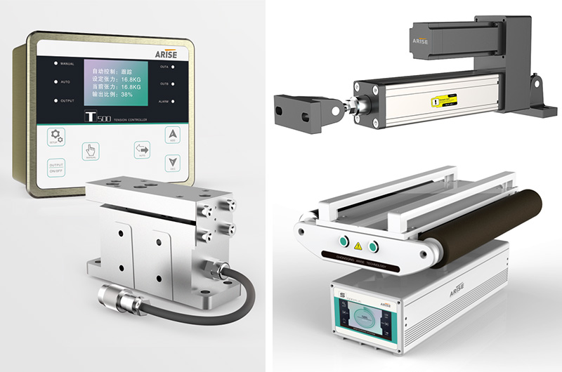
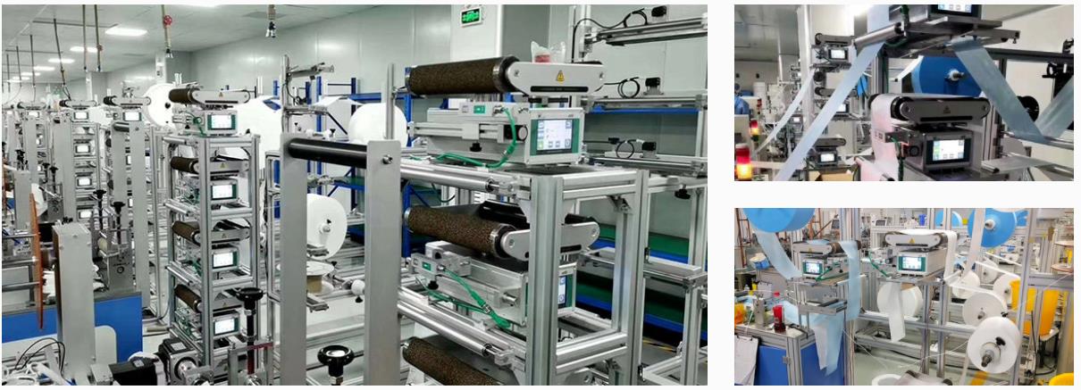
In industries reliant on continuous web handling and processing, such as printing, packaging, textiles, and paper manufacturing, web guide machines are indispensable. These web guide systems are instrumental in achieving precise web alignment and control, leading to enhanced product quality, reduced waste, and heightened production efficiency. However, with a multitude of options available in the market, choosing the right web guide machine tailored to your specific requirements can be a challenging task. In this article, we delve into the process of selecting the ideal web guide machine by exploring the different types of web guide systems and the key factors to take into account when making this critical decision for your industry.
Types of Web Guide Machines:
Edge Web Guiding Systems: These are the most commonly used web guide systems. They monitor and manage the web's position by detecting its edges. Sensors on either side of the web continuously track its edge positions, and the control system makes adjustments to keep the web centered and aligned.
Center Web Guiding Systems: Also known as line guiding systems, these systems regulate the web based on its centerline. A single sensor detects the web's center location and adjusts the guiding mechanism accordingly. Center guiding systems are especially effective when dealing with irregular or inconsistent edge materials.
Sensor-Based Web Guide Machines: These systems employ various sensor technologies to detect the web's position and make necessary adjustments. Sensor options include ultrasonic sensors, infrared sensors, line-scan cameras, and laser sensors, with each offering distinct advantages based on factors such as the web material, production environment, and required precision.
Hydraulic Web Guide Machines: Hydraulic web guide machines utilize hydraulic actuators to make real-time adjustments to the web's position. They excel in heavy-duty applications where substantial force is required for precise web guidance.
Pneumatic Web Guide Machines: Pneumatic actuators control the web's position in these machines. They are known for their rapid responsiveness and precise adjustments, making them well-suited for high-speed manufacturing processes.
Electric Web Guide Machines: Electric actuators are responsible for controlling the web's position in electric web guide machines. They are often preferred for their low energy consumption and ease of integration with other automated systems.
Factors to Consider When Choosing a Web Guide Machine for Your Industry:
Selecting the right web guide machine is a decision that can significantly impact production efficiency, product quality, and overall operational effectiveness. Here are the key factors to consider:
Types of Web Material: Evaluate the web material used in your industry, such as paper, film, foil, fabric, or non-woven material. The web guide machine must be compatible with the specific properties and requirements of the material you are working with.
Web Width and Speed: Determine the machine's maximum and minimum web widths and production speeds to ensure it can accommodate your entire range of web widths and speeds.
Alignment Precision: Identify the level of precision required for your production process. Industries like printing and converting may necessitate web guide machines equipped with advanced sensing technology and precise control mechanisms.
Guiding System Type: Choose the guiding system type that best suits your needs. Edge guiding systems are typically used for continuous and constant webs, while center guiding systems are preferred when dealing with irregular or inconsistent edge materials.
Sensor Technology: Examine the sensor technologies used in the web guide machine and select the one that aligns with your web material and guiding requirements.
Control Mechanism: Consider the control mechanisms available for the web guide machine, ranging from automatic systems that make real-time adjustments based on sensor feedback to manual control requiring operator interaction. Your choice depends on the desired level of automation and operator engagement.
Integration with Existing Equipment: Ensure the web guide machine can seamlessly integrate with your existing manufacturing equipment and automation systems. Compatibility with other machinery is essential for effective operation and communication between systems.
Web Tension Control: If web tension management is critical for your process, consider web guide machines equipped with integrated tension control functions. Maintaining web stability is essential for product quality.
Maintenance and Support: Assess the maintenance requirements of the web guide machines and the availability of technical support from the manufacturer or supplier. Regular maintenance and reliable support are essential for the machine's longevity and peak performance.
Cost and Return on Investment (ROI): While the initial cost is a factor, consider the long-term return on investment. A high-quality web guide machine that enhances production efficiency and product quality can yield substantial long-term benefits.
Training and User-Friendliness: Evaluate the machine's user-friendliness and the availability of operator training. Proper training ensures operators can efficiently utilize the machine and address minor issues.
Summary:
Selecting the right web guide machine is a pivotal decision with the potential to impact the efficiency and productivity of your manufacturing process significantly. A well-chosen web guide machine can lead to improved product quality, reduced waste, and more efficient production processes, all of which contribute to the overall success of your company.
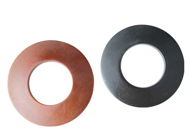
Belleville springs, often referred to as disc springs, owe their name to the French engineer Belleville, who invented this unique spring. These springs take on a conical disc shape and can be utilized individually, in series, or in parallel. Disc springs are defined by four key parameters: outer diameter, inner diameter, thickness, and height.
Key Features of Belleville Springs:
Energy Storage: When subjected to a load, Belleville springs deform and store potential energy.
Energy Release: These springs can release stored energy when slack or reduced loads are encountered.
Uniform Stress Distribution: Belleville springs offer even stress distribution from the inner to outer edges, enabling precise control with low stroke and high compensation force.
Shock Absorption: Known for their remarkable shock-absorbing capacity, Belleville springs can withstand substantial loads with minimal deformation, making them an excellent choice for applications with limited axial space.
Versatile Combinations: Belleville springs can be used in various combinations, including superposition, inversion, and compound arrangements. This flexibility allows for a wide range of spring characteristics to suit specific applications. Mixing springs with different thicknesses and quantities further enhances versatility.
Variable Stiffness: By adjusting the height-to-thickness ratio of the conical disc or by combining discs of varying thicknesses or quantities, Belleville springs can exhibit different stiffness characteristics. This enables customization of spring behavior, offering linear, increasing, decreasing, or combined responses.
Ease of Maintenance: When damage occurs to a Belleville spring, only the affected disc needs to be replaced, simplifying maintenance and repair.
Concentric Force Transmission: Due to their annular shape, Belleville springs transmit force concentrically, ensuring even force distribution.

Applications of Disc Springs:
Belleville springs find widespread application in various industries, including:
Metallurgy: They serve as strong buffers and shock absorbers in heavy machinery.
Engineering: Commonly used in precision applications where energy storage and release are crucial.
Electric Power: They play a role in power generation and distribution equipment.
Machine Tools: These springs are components in machinery that demand precision and control.
Construction: Used in construction equipment and machinery.
Safety Valves and Pressure Reducing Valves: Employed to provide essential spring force in these types of valves.
As a Chinese manufacturer specializing in Belleville springs, KENENG offers a diverse range of materials, sizes, surface treatments, and certifications. Custom springs can be produced based on customer-provided drawings, and their products have earned a strong reputation among both domestic and international collaborative enterprises. For custom spring needs, KENENG provides the expertise of professional spring design and manufacturing engineers. Don't hesitate to reach out for their services.
Open hole well logging is a crucial technique employed in the oil and gas industry for acquiring valuable insights into subsurface formations. This process involves inserting specialized equipment into an uncased wellbore to assess parameters such as resistivity, porosity, and rock density. In this context, the open hole well logging simulator emerges as a groundbreaking tool for training professionals and enhancing their expertise in interpreting well logging data.

The open hole well logging simulator is a sophisticated software program designed to replicate real-world well logging conditions. It creates a virtual environment where users can simulate and practice data interpretation from an open hole wellbore, offering an immersive learning experience that simplifies complex well logging concepts.
Features and Benefits of an Open Hole Well Logging Simulator
Realistic Data Generation: The simulator generates well logging data that closely mimics real readings, allowing users to simulate actual well logging settings and enhance their comprehension of logging tool responses and interpretations.
Variety of Logging Tools: The simulator includes a range of logging instruments commonly used in open hole well logging, such as resistivity, neutron, density, acoustic, and gamma-ray logs. Users can practice deploying and interpreting these diverse logging mechanisms.
Interactive Interface: The simulator features a user-friendly interface that enables hands-on simulation, parameter adjustments, and interactive data analysis. This interactive approach fosters active learning and skill development.
Multiple Scenarios: The simulator offers various well logging scenarios, each simulating distinct geological formations and wellbore conditions. This allows users to refine their interpretation skills under different contexts, enhancing their adaptability in real-world situations.
Data Visualization and Analysis: Advanced data visualization and analysis tools are integrated into the simulator, allowing users to plot and analyze the simulated well logging data to gain a deeper understanding of reservoir features and rock formations.
Calibration and Validation: The simulator ensures data accuracy by calibrating the simulated measurements against known values, guaranteeing dependable training results for users.
Error and Uncertainty Simulation: The simulator incorporates errors and uncertainties into synthetic data to mirror real-world challenges, assisting users in developing the ability to identify and mitigate uncertainty in actual well logging data.
User Progress Tracking: Throughout training sessions, the simulator tracks user development and performance, providing users with insights into their progress and areas for improvement.
Scenario Customization: Users can tailor parameters like wellbore trajectory, formation features, and logging tool configurations to create personalized scenarios, offering customized training experiences to meet individual learning goals.
Simulation Speed Control: Users can adjust the simulation speed to observe data collection and responses in real-time or slow motion, enhancing their understanding.
Virtual Wellbore Environment: The well logging simulator creates a lifelike wellbore environment complete with geological formations, wellbore pathways, and logging tool responses, immersing users in a realistic learning experience.
Error Diagnosis and Troubleshooting: The simulator includes tools for error diagnosis and troubleshooting to help users identify and rectify common well logging data interpretation errors.

Common Applications of an Open Hole Well Logging Simulator
Training and Education: Open hole well logging simulators are widely used in universities, technical schools, and training centers to educate and train professionals, allowing them to practice and enhance their interpretation skills in a cost-effective and risk-free environment.
Skill Enhancement: Even experienced experts can benefit from the simulator, using it as a valuable resource for refreshing and updating their well logging interpretation skills.
Research and Development: Researchers can utilize the simulator for testing novel well log interpretation methods and approaches, providing a controlled setting for experimenting with various scenarios and assessing the effectiveness of their methods.
Quality Assurance and Performance Evaluation: Oilfield service companies can employ the simulator to assess the competence of their well logging teams, ensuring high-quality well logging data interpretation and identifying areas for improvement.
Well Log Analysis Training: The simulator can be integrated into well log analysis training programs, preparing trainees for real-world well logging missions by allowing them to practice with various logging tools and analyze diverse data sets.
Reservoir Evaluation Practice: The simulator aids in practicing reservoir evaluation and subsurface formation characterization, facilitating the estimation of key reservoir parameters such as porosity, permeability, and fluid saturation for informed reservoir management decisions.
Team Collaboration and Training: Well logging teams can collaborate in a simulated environment to improve teamwork, communication skills, and problem-solving abilities, thereby enhancing their overall effectiveness.
In summary, open hole well logging simulators are essential tools shaping the future of well logging and reservoir evaluation. They will play a pivotal role in enhancing the knowledge and skills of professionals in the oil and gas industry.