The oil and gas industry, a vast and intricate realm, relies on a symphony of engineering marvels to explore and extract hydrocarbons from beneath the Earth's surface. At the heart of this intricate choreography is the drilling system, a complex ensemble of technologies, equipment, and methodologies that pierce through layers of rock and sediment to unlock the world's energy resources. In this article, we delve into the world of drilling systems that are propelling the oil and gas industry into a new era of efficiency, safety, and resource optimization.
The Essence of Drilling Systems:
Drilling systems are the lifeblood of the oil and gas industry, facilitating the exploration and extraction of Earth's hidden treasures. These intricate systems amalgamate cutting-edge technologies, machinery, and expertise to delve into the depths of the subsurface, unlocking coveted hydrocarbon reservoirs.
These systems orchestrate a synchronized dance of drill bits, drill strings, hoisting mechanisms, and mud circulation, culminating in the creation of wellbores. This intricate choreography not only grants access to precious resources but also embodies precision, innovation, and unwavering determination. Through the interplay of components like well control equipment, casing, and logging tools, drilling systems ensure operational integrity while guarding against potential hazards, all while harnessing the power of modern engineering.
As the industry evolves, drilling systems continue to be the backbone of oil and gas endeavors, embodying the relentless pursuit of energy excellence while reshaping the global energy landscape.
The Core Components of Drilling Systems:
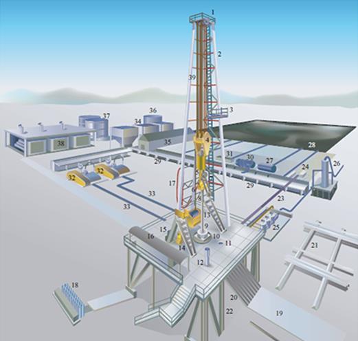
The core components of drilling systems form an intricate web of technologies and equipment essential for the successful exploration and extraction of oil and gas resources. These components collaborate seamlessly to drive the drilling process forward, ensuring efficiency, safety, and optimal wellbore creation.
Drill Bit: The drill bit serves as the point of contact between the rig and the Earth's crust. Innovative drill bit designs, such as polycrystalline diamond compact (PDC) and roller cone bits, are engineered to cut through various rock formations with precision.
Drill String: Comprising the drill pipe, drill collars, and other accessories, the drill string provides the conduit for transmitting power and torque from the rig to the drill bit.
Mud Circulation System: This system involves drilling fluid, often referred to as "mud," which serves to lubricate the drill bit, cool the drill string, and carry cuttings to the surface. Mud also provides crucial pressure control to prevent blowouts.
Hoisting System: The hoisting system employs the drawworks to raise and lower the drill string, enabling vertical movement within the wellbore.
Rotating System: The rotating system powers the rotation of the drill string and bit, allowing for efficient drilling of the wellbore.
Together, these core components harmonize their functions, creating a symphony of engineering prowess that characterizes drilling systems in the oil and gas industry.

Benefits and Impact of Drilling Systems:
Efficiency Enhancement: Modern drilling systems optimize drilling speed, reduce non-productive time, and minimize downtime, contributing to more efficient operations.
Safety Advancements: Drilling systems incorporate state-of-the-art safety features, real-time monitoring, and automated controls to enhance personnel safety and prevent accidents.
Resource Optimization: By maximizing equipment utilization and minimizing operational inefficiencies, drilling systems contribute to cost savings and resource optimization.
Environmental Considerations: Advanced drilling technologies aim to minimize environmental impact through reduced emissions, efficient mud management, and optimized wellbore integrity.
Simulation of Drilling Systems:
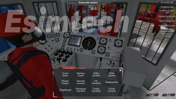
In the dynamic realm of oil and gas exploration, the pursuit of efficiency, safety, and precision has spurred the evolution of drilling systems. Leading this transformation is simulation technology, an innovative approach that empowers the industry to test, optimize, and revolutionize drilling operations in virtual environments. Drilling systems simulations bring together the intricacies of engineering, data analysis, and real-world scenarios to create a digital playground for engineers, operators, and decision-makers.
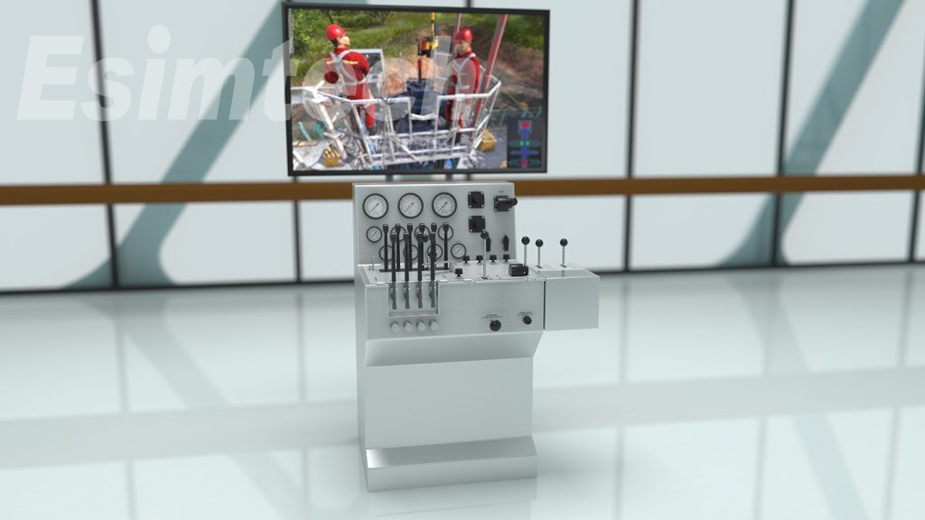
To provide an authentic experience of oil drilling and equip students with relevant knowledge and skills, Esimtech has developed a drilling and well control simulation system. This system faithfully reproduces the working atmosphere of oil drilling operations. Through this simulation technology, individuals can gain a comprehensive understanding of the drilling system and master its application.
Innovations and Transformation in Drilling Systems:
In the ever-evolving landscape of the oil and gas industry, innovation stands as the driving force behind the transformation of drilling systems. Pioneering technologies are reshaping conventional practices, enhancing efficiency, safety, and environmental responsibility. These innovations are not only propelling the industry forward but also redefining its capabilities and potential.
Automated Drilling: Automation has revolutionized drilling operations by enabling real-time monitoring, data analysis, and decision-making. Automated drilling systems utilize sensors and advanced algorithms to optimize drilling parameters, detect anomalies, and adjust operations in response to changing downhole conditions.
Directional Drilling: Advanced directional drilling techniques, such as rotary steerable systems and electromagnetic guidance, enable precise wellbore placement and access to previously inaccessible reservoirs, maximizing resource recovery and reservoir drainage.
Managed Pressure Drilling (MPD): MPD techniques control wellbore pressure to prevent kicks and losses, enhancing safety and efficiency. By optimizing pressure, MPD enables drilling through challenging formations while minimizing formation damage.
Dual Gradient Drilling: This technique uses two different types of drilling fluid to balance wellbore pressures, making drilling in challenging environments, such as deepwater, more manageable.
Casing While Drilling (CWD): CWD systems allow operators to simultaneously drill and install casing, saving time and reducing the risk of wellbore instability.
These innovations are ushering in a new era of drilling systems, where precision, automation, and sustainability converge to unlock previously untapped potential in the oil and gas industry. As technology continues to advance, the industry is poised to reach greater depths, access more challenging reservoirs, and conduct operations with unprecedented efficiency and environmental responsibility.
Conclusion:
Drilling systems represent the dynamic heart of the oil and gas industry, combining cutting-edge technology, engineering prowess, and operational expertise to unlock vital energy resources.
Simulation-driven drilling systems have emerged as a game-changing force in the oil and gas industry, offering a virtual canvas for exploration and innovation. As this technology continues to evolve, the realm of drilling systems simulation promises to usher in a new era of efficiency, safety, and sustainability, shaping the future of oil and gas exploration and production.
The laboratory electronic analytical balance stands as an indispensable weighing instrument within laboratory settings. Its presence is not merely recommended but required for precise measurements and experiments. In the realm of electronic laboratory balances, the key to assessing their quality lies in their performance. Although some might argue against the relevance of four fundamental measurement criteria in evaluating electronic laboratory balances, the author maintains that these four parameters remain foundational for assessing their quality.

Stability of the Balance:
The stability of a balance signifies its ability to return to its initial equilibrium position after being subjected to disturbances. In electronic balances, this equilibrium is reflected in the analog or digital indication value. A stable electronic balance will always return to its initial indicated value after momentary disruptions. Without this stability, an electronic balance is practically unusable.
Balance Sensitivity:
Balance sensitivity pertains to the balance's capability to detect changes in the mass placed on the weighing pan. In the context of electronic laboratory balances, this sensitivity is typically measured using graduation sensitivity or digital (division) sensitivity. The higher the sensitivity, the better the balance can detect even minuscule changes in mass. Sensitivity is, therefore, a critical factor in evaluating the quality of electronic laboratory balances.
Correctness of the Balance:
Correctness refers to the accuracy of the balance's indication in relation to the true value. This accuracy can be assessed by examining the systematic error in the balance indication. For electronic balances, correctness is not only seen in the balance arm ratio for lever electronic laboratory balances but also in the analog or digital scale indications when loads are placed at various points on the balance plate. Correctness remains a significant parameter for assessing balance quality, whether it's mechanical or electronic.
Invariance of Balance Indication:
The invariance of balance indication relates to the consistency of measurement results obtained when the balance measures the same object multiple times under identical conditions. This aspect includes controlling the repeatability, reproducibility, zero position, and return of the electronic balance, as well as monitoring drift in the balance indication value after an extended period of loading.

Selecting an Electronic Analytical Balance:
When purchasing electronic laboratory balances, it's crucial for users to choose a balance that aligns with their weighing accuracy and range requirements. Here are some considerations for making the right choice:
Balance Accuracy: Ensure the balance accuracy matches your measurement requirements. Avoid overinvestment in accuracy that exceeds your needs. Consider the typical sample weights you work with, which should account for 60-80% of the balance's weighing range.
Usage Occasions: Select balances that suit the environmental conditions in your lab. High-grade balances are suitable for controlled environments, while simple, rugged balances are better for outdoor or challenging conditions.
Quality Assurance and Additional Functions: Prioritize trusted quality assurance and consider additional features that might facilitate your experiments.
Cost-Effectiveness: Strive for a balance between quality and price. Seek products that offer the best cost-performance ratio, ensuring efficiency in resource utilization.
Annual Usage Costs: Consider the long-term costs, including maintenance and replacement expenses. A more expensive, durable balance might prove more cost-effective over time.
Compatibility and Tolerance: Evaluate how well the balance accommodates different operators and environmental factors, offering consistent and reliable results.
After-Sales Service: Choose products from reputable manufacturers with good after-sales support and the potential for function expansion.
Humanized Design: Opt for balances with user-friendly designs that minimize the risk of operational errors and offer a comfortable user experience.
In conclusion, the selection of an electronic analytical balance is a critical decision that can significantly impact the accuracy and efficiency of laboratory work. By considering these factors, users can make informed choices that align with their specific needs and laboratory conditions.
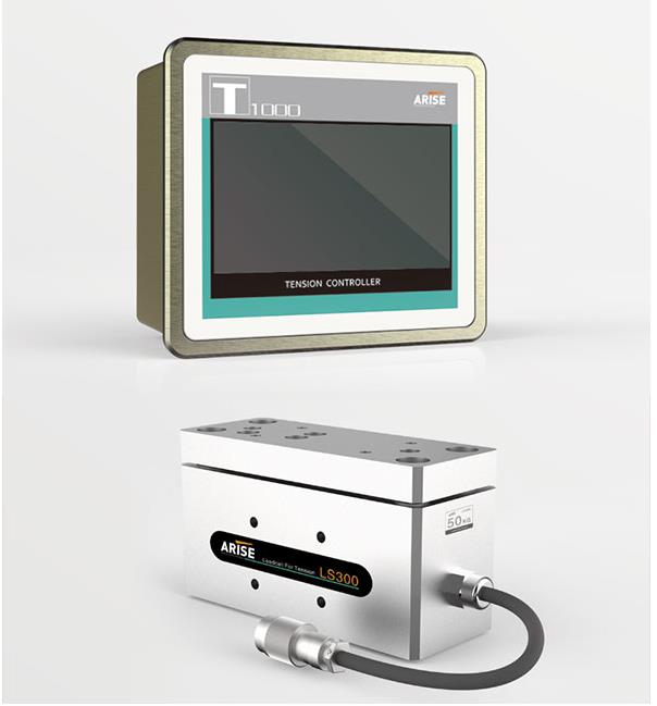
Web tension control is indispensable in numerous industries, including printing, packaging, paper manufacturing, and textile production, where continuous materials or "webs" are processed. Ensuring optimal web tension is vital for product quality and manufacturing efficiency. However, web tension control presents its fair share of challenges that require innovative solutions. In this article, we will delve into these common challenges of web tension control and explore strategies to overcome them.

Common Challenges in Web Tension Control
1. Variability in Web Material Properties
Web materials often exhibit variations in thickness, width, and stretchability. These differences can make it challenging to maintain precise tension control. For instance, sections with varying thickness may require different tension levels.
2. Dynamic Changes in Speed
Web speeds can fluctuate in manufacturing processes due to accelerations and decelerations. These speed changes can affect web tension and, if not managed properly, lead to web breaks or low-quality output.
3. Web Wrinkling and Folding
Web tension controller must prevent web wrinkling or folding, which can damage materials and disrupt manufacturing. Wrinkles may result from issues such as misaligned rollers or inadequate web spreading.
4. Slippage and Snagging
Slippage between the web and rollers can result in inconsistent tension control, while web snagging or jamming can halt production and damage the material.
5. Environmental Factors
Environmental conditions like temperature and humidity can impact web tension control. Changes in these conditions may cause the web material to expand or contract, affecting tension.
6. Complex Web Paths
In certain processes, web materials follow intricate paths with multiple rollers and turns, making precise tension control challenging.
Strategies to Overcome Web Tension Control Challenges
Variability in Web Material Properties
Web Inspection: Regularly inspect the web material for variations in thickness, width, or stretchability, using web inspection vision systems to identify and classify variances.
Tension Compensation: Use tension zones or dancer rollers that can respond to material changes, allowing you to adjust tension control parameters for different sections of the web.
Dynamic Changes in Speed
Closed-Loop Control: Invest in closed-loop tension control systems that can react to changes in web speed in real-time. These systems use sensors to detect fluctuations and adjust tension accordingly.
Web Wrinkling and Folding
Proper Roller Alignment: Ensure rollers are precisely positioned and parallel to the web path to prevent wrinkles. Roller guides and edge sensors can help maintain alignment.
Web Spreading: Use web spreading devices or air bars to keep the web flat and wrinkle-free, aiding in the even distribution of strain across the web.
Advanced Control Algorithms: Employ tension control systems with advanced control algorithms capable of detecting and correcting wrinkles as they occur.
Slippage and Snagging
Surface Properties: Choose rollers with appropriate surface properties, such as coatings or grips, to minimize slippage. Ensure that rollers and guides are kept clean and well-maintained to prevent snags.
Environmental Factors
Controlled Environment: Manage temperature and humidity in the manufacturing area to maintain a controlled environment. Use sensors to monitor environmental conditions and adjust tension control systems accordingly.
Complex Web Paths
Accurate Alignment: Pay close attention to roller alignment in complex web paths. Implement tension zones at key points to manage tension more effectively.
Customized Tension Zones: Design tension zones tailored to the specific requirements of complex web paths. Tension control systems should be adaptable and configurable to meet unique process needs.
Additional Best Practices
Regular Maintenance: Implement routine maintenance to ensure that all tension control components, including rollers, sensors, and control systems, are in good working order.
Operator Training: Provide comprehensive training to operators and technicians to equip them with the knowledge to manage web tension effectively.
Data Analysis: Use data logging and analysis tools to track tension fluctuations and identify patterns or trends, aiding in the identification of the root causes of tension issues.
Continuous Improvement: Foster a culture of continuous improvement by seeking feedback from operators and engineers to refine tension control processes and systems.
Conclusion
The importance of web tension control cannot be overstated in industries relying on continuous web materials. By addressing the challenges of maintaining precise web tension through innovative solutions and best practices, manufacturers can ensure product quality, enhance process efficiency, and minimize downtime. Employing modern tension control technologies, implementing rigorous quality control procedures, and understanding the dynamics of web materials are key to achieving optimal outcomes in production processes.
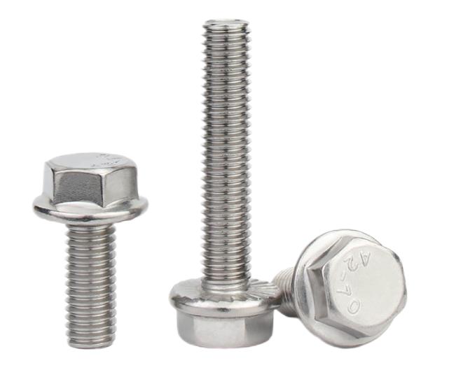
Aerospace bolts play a vital role in transferring shear and tensile loads, finding extensive application in areas that bear heavy concentrated loads or require disassembly within the realm of aviation. In this article, we explore the standards governing bolt threads in the aerospace industry, offering insights into the various specifications, fit quality, and identification symbols. These standards provide essential guidelines for selecting the right bolts for aviation applications.
1. Standards for Bolt Threads
In the aerospace industry, the standards for bolt threads are critical for ensuring the safety and integrity of aircraft structures. There are several key standards to consider:
a. American National Coarse Threads
b. American National Fine Threads
c. American Standard United Coarse Threads
d. American Standard United Fine Threads
These standards differentiate primarily based on two key factors:
1. Thread Pitch: Coarse and fine series threads of the same size share the same nominal thread diameter but differ in the number of threads per inch.
2. Tolerance Distribution: Each standard has distinct tolerance specifications for threads with a one-inch diameter. For instance, NF regulation utilizes 14 teeth per inch, represented as 1-14NF, while UNF regulation employs 12 teeth per inch, represented as 1-12UNF.
2. Fit Quality
The grade of a thread indicates the tightness of the fit between threaded parts, and it ranges from Grade 1 to Grade 5:
a. Grade 1 (Loose Fit): This level of fit allows for easy manual turning of the nut.
b. Grade 2 (Free Fit): Typically used for aerospace screws due to its specific requirements.
c. Grade 3 (Medium Fit): Commonly used for aerospace bolts where a secure yet manageable fit is essential.
d. Grade 4 and 5 (Tight Fit): These grades require a wrench for nut tightening. A higher grade corresponds to a tighter fit.
3. Identification Symbols
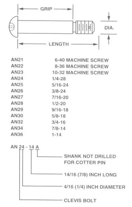
Bolt identification includes details such as diameter, length, and material. The unit of measurement for diameter is 1/16 inch, while the unit for bolt rod length is 1/8 inch. Material specifications are conveyed using English letters or symbols:
"C" denotes stainless steel.
"DD" signifies 2024 aluminum alloy.
"-" is used for nickel alloy steel.
General Standard Bolts in the Aerospace Industry
Hexagonal Head Bolt
The hexagonal head bolt is a widely used standard aviation bolt suitable for aircraft structure assembly, capable of withstanding tensile and shear loads. It adheres to the AN model specification standard and employs fine threads. Materials include chrome-plated nickel steel, stainless steel, and 2024 aluminum alloy.
Model Specification Code:
Example: AN 3 DD 14A
"AN" represents the standard bolt of USAF Navy specification.
"3" denotes a bolt diameter of 3/16 inch.
"DD" indicates the use of 2024 aluminum alloy.
"14" signifies a rod length of 1.5 inches.
"A" indicates the absence of a safety hole at the screw tail.
Engine Bolts Drilled in the Head
These bolts, identified by model specification codes ranging from AN73 to AN81 and MS20073 to MS20074, have slightly thicker heads with a through hole for a fuse. They possess the same tensile and shear strength as ordinary bolts.
Hexagon Socket Head Bolt
These bolts, bearing model specification codes MS20004 to MS20024, come in various diameters from 4/16 inch to 24/16 inch. They are made of high-strength steel and are not interchangeable with AN series hexagon bolts. These bolts are primarily used for connecting parts that bear both tensile and shear combined stresses.
For steel parts, the installation hole should be chamfered to allow the fillet to sink into the hole.
When installing on aluminum alloy parts, an MS20002C washer should be used beneath the bolt head.
Slotted Cheese Head Bolt
Slotted cheese head bolts are identified by model specification codes like AN21, AN22, and AN23, where the digits represent thread sizes (e.g., "6-40," "8-36," "10-32"). These bolts have fine threads (NF) and are ideal for bearing shear loads, often used as hinge pivot pins in rotating parts.
In Conclusion
Understanding the standards for bolt threads in the aerospace industry is crucial for selecting the right fasteners for aviation applications. The specifications, fit quality, and identification symbols of these bolts ensure the safety and reliability of aerospace structures. Proper bolt selection is an essential aspect of aviation engineering, contributing to the overall safety and performance of aircraft.Snubbing operations play a crucial role in well interventions by facilitating the controlled insertion and extraction of coiled tubing or jointed pipe into live wells. Ensuring the efficiency and safety of these operations requires well-trained operators with finely honed skills. To meet this need, the full-size snubbing simulator has emerged as a groundbreaking technology, offering snubbing operators an immersive and realistic training environment. In this article, we will explore the significance of the full-size snubbing simulator and its profound impact on the evolution of well intervention practices in the oil and gas industry.
Unveiling the Full-Size Snubbing Simulator
The full-size snubbing simulator stands as an innovative training tool designed to replicate real-world snubbing operations within a safe and immersive setting. Employing state-of-the-art technology such as virtual reality, physics-based modeling, and interactive simulations, this simulator provides operators with a hands-on, lifelike learning experience for snubbing operations.
At its core, the full-size snubbing simulator aims to enhance snubbing operator training and skill development. It meticulously mimics the configuration of snubbing units, control panels, downhole tools, and well conditions, allowing operators to interact with physical replicas of equipment and engage in various snubbing procedures in a controlled environment. This replication extends to the functionality, responses, and limitations of the actual equipment, providing operators with invaluable familiarity with their tools.
Transforming Well Intervention in the Oil and Gas Industry
The adoption of the full-size snubbing simulator promises to revolutionize well intervention practices across various dimensions in the oil and gas industry.
1. Enhancing Safety
Safety is paramount in the oil and gas industry, particularly during well intervention procedures. The full-size snubbing simulator offers a secure and controlled learning environment where operators can practice their skills without exposure to the inherent dangers of real field operations. This training equips operators to confidently manage real-world situations safely and effectively.
2. Skill Development and Proficiency
The simulator fosters muscle memory and the mastery of skills in a realistic environment, promoting hands-on learning. Operators can enhance their competency, efficiency, and decision-making abilities by engaging in a range of snubbing interventions. This, in turn, leads to more successful well interventions, reduced downtime, and optimized well productivity.
3. Cost-Effective Training
Traditional live field training for snubbing operations can be both costly and time-consuming. The Full-Size Snubbing Simulator eliminates the need for physical installations and lowers operational costs, offering a cost-effective alternative. Companies can streamline their training programs and resource management, resulting in substantial cost savings.
4. Customization and Versatility
The full-size snubbing simulator's adaptability allows operators to create training scenarios tailored to specific well conditions and intervention challenges. This versatility ensures that operators receive specialized and comprehensive training, enabling them to effectively address a wide range of real-world snubbing situations.

5. Improving Operational Efficiency
When skilled operators are trained using the Full-Size Snubbing Simulator, snubbing operations become more efficient and precise. Optimized well interventions lead to increased well production, reduced downtime, and enhanced reservoir performance, ultimately improving overall operational efficiency and the industry's success.
6. Accelerated Learning and Continuous Improvement
The simulator facilitates repetitive practice and ongoing skill development. Operators can run simulations repeatedly, learning from their mistakes and continuously improving their skills and strategies. This fosters a culture of learning and ongoing growth, ensuring that operators remain updated on industry best practices and technological advancements.
7. Technological Advancements and Innovation
The adoption of the full-size snubbing simulator underscores the industry's commitment to embracing cutting-edge technologies. As the simulator evolves, incorporating advancements like virtual reality, artificial intelligence, and data analytics, it propels the industry toward more advanced and innovative well intervention techniques.
In Conclusion
The full-size snubbing simulator stands as a transformative tool, revolutionizing snubbing operator training and skill development in the oil and gas industry. As the industry continues to embrace the latest technologies, the snubbing simulator is a crucial catalyst for optimizing snubbing operation techniques and elevating the overall performance of well interventions in the oil and gas sector.