Kjeldahl nitrogen analyzers play a crucial role in laboratories, facilitating the accurate determination of nitrogen content in various substances. However, like any complex instrument, these analyzers can encounter issues during operation. This article aims to provide a comprehensive guide to common problems associated with Kjeldahl nitrogen analyzers and practical solutions to address them.

Violent Rolling During Distillation:
Issue: The Kjeldahl nitrogen analyzer rolls violently during distillation.
Solution: This is typically caused by a large amount of water vapor entering the digestive tube. While it may appear concerning, the Kjeldahl nitrogen analyzer is equipped with an overpressure protection device to maintain safe internal pressure.
Water Quality Requirements:
Issue: What are the water quality requirements for the Kjeldahl nitrogen analyzer?
Solution: Use distilled water or pure water in the distilled water barrel. If the analyzer is unused for an extended period, release the water in the distiller.
No Sound When Turned On:
Issue: The Kjeldahl nitrogen analyzer produces no sound when turned on.
Solution: Check if the red light on the power switch is on. If the fuse is blown, locate it in the black case 5 cm away from the power switch interface inside the machine.

Failure to Add Water to the Distiller:
Issue: The Kjeldahl nitrogen analyzer does not add water to the distiller after being turned on.
Solution: Check for leaks in the distilled water bucket, ensure the water level is sufficient, and verify correct connections. Confirm that the drain valve is closed.
Steamer Not Heating:
Issue: The steamer of the Kjeldahl nitrogen analyzer does not heat and cannot produce steam.
Solution: If alkali can be added but no steam is produced, the heating wire may be burnt out. Use a multimeter to check the positive and negative electrodes.
Loud Working Sound:
Issue: The Kjeldahl nitrogen analyzer produces a loud working sound.
Solution: This is a normal sound resulting from the air pump inside the analyzer.
Failure to Add Alkali:
Issue: The Kjeldahl nitrogen analyzer cannot add alkali, and there is no sound during the process.
Solution: Check for alkali barrel leaks and ensure the machine operates normally when inflated with air. If the analyzer has been in use for a long time, crystallization inside the alkali pipe may impede flow.
Smoke-Like Gas Emission:
Issue: Smoke-like gas comes out from the top during operation.
Solution: Ensure the cooling water inlet faucet is open. Closed or low water volume can result in uncondensed steam, creating the appearance of smoke.
Sucking Back of White Tube:
Issue: The white tube in the digestive tube sucks back during operation.
Solution: Check if the gas valve closes promptly when the Kjeldahl nitrogen analyzer stops working. If not, pierce small holes in the white tube or replace the faulty air valve.
Regular Sound Every 3-5 Seconds:
Issue: The Kjeldahl nitrogen analyzer makes a sound every 3-5 seconds during operation.
Solution: This periodic sound is normal. It occurs as the distiller continues to heat, generating water vapor, and the machine automatically opens the water valve to replenish water.

Conclusion
Troubleshooting common problems in Kjeldahl nitrogen analyzers involves a systematic approach to identify and address issues promptly. By understanding the potential challenges and implementing the provided solutions, operators can ensure the reliable and efficient performance of these essential laboratory instruments. Regular maintenance and adherence to operational guidelines contribute to the longevity and accuracy of Kjeldahl nitrogen analyzers in analytical processes.
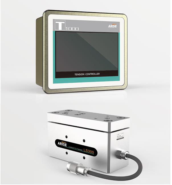
In today's rapidly evolving industrial landscape, where efficiency and cost-effectiveness are paramount, the need to meet production demands often requires the utilization of older machinery in sectors like printing, packaging, and textiles. However, while these machines may still be operational, their outdated features and lack of modern technology can hinder productivity and compromise product quality. The solution? Retrofitting older machines with web tension control systems, a pragmatic alternative that brings outdated equipment up to modern standards.

The Significance of Retrofitting with Web Tension Control Systems:
Web tension control is a critical element in manufacturing processes involving continuous materials such as paper, film, fabric, or metal. Ensuring the precise movement of materials through a machine is essential for maintaining product quality, minimizing waste, and reducing downtime.
Benefits of Retrofitting with Web Tension Control Systems:
1. Improved Product Quality:
Consistent web tension leads to fewer faults, translating to higher-quality goods that enhance a company's reputation and client satisfaction.
2. Enhanced Efficiency:
Reduced downtime and increased production rates contribute to overall efficiency, directly impacting the bottom line of manufacturing operations.
3. Cost Savings:
Less waste, lower maintenance costs, and improved energy efficiency collectively contribute to substantial cost savings and increased profitability.
4. Sustainability:
Reduced waste and energy consumption not only save money but also align manufacturing operations with environmental sustainability goals.
5. Prolonged Machine Life:
Retrofitting can extend the life of aging machinery, postponing the need for expensive replacements and providing a sustainable approach to equipment management.
6. Data-Driven Decision Making:
Modern tension control systems offer valuable data and analytics, enabling informed decision-making and process optimization.
The Retrofitting Process with Web Tension Control Systems:
Assessment:
Conduct a thorough evaluation of current equipment to identify areas where web tension control is critical to the production process.
System Selection:
Choose a web tension controller based on specific needs, considering factors such as web material, machine specifications, and production speed.
Installation:
Professional installation by experts familiar with the intricacies of integrating modern control systems with older equipment. Mechanical and electrical adjustments may be necessary for compatibility.
Calibration:
Calibrate the system to provide precise tension control, including setting up sensors, establishing tension zones, and adjusting control settings.
Training:
Train operators and maintenance personnel to efficiently operate and manage the tension control system.
Integration:
Seamlessly integrate the new web tension control system into the existing control infrastructure, such as PLCs (Programmable Logic Controllers) or SCADA (Supervisory Control and Data Acquisition) systems, for streamlined communication and data exchange.
Case Studies of Retrofitting Older Machines with Web Tension Control Systems:
Case Study 1: Printing Industry - ABC Printing Company
Challenge:
Aging web offset printing press lacking precise web tension control, resulting in inconsistent print quality and frequent paper jams.
Solution:
Replacement of the antiquated press with a modern web tension control system.
Results:
Significant improvements in product quality, increased productivity, waste reduction, and simplified maintenance.
Case Study 2: Textile Industry - XYZ Textile Mills
Challenge:
Weaving looms experiencing yarn breakage, misalignment, and variable fabric quality due to the lack of precise web tension control.
Solution:
Retrofitting of weaving looms with a modern web tension control system.
Results:
Enhanced fabric quality, increased productivity, and cost savings through reduced material waste.
These case studies underscore how retrofitting older machines with modern web tension control systems can positively impact product quality, productivity, cost savings, and sustainability, making it a prudent investment for manufacturing businesses.
Conclusion:
For companies seeking to enhance the efficiency and productivity of existing production processes, retrofitting older machines with web tension control systems proves to be a strategic and cost-effective solution. This method ensures that aging machinery can compete with modern counterparts, resulting in improved product quality, waste reduction, and overall cost savings. By carefully assessing machinery, selecting the appropriate control system, and investing in professional installation and training, manufacturing operations can remain competitive and forward-looking in an ever-evolving industrial landscape.
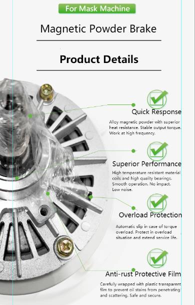
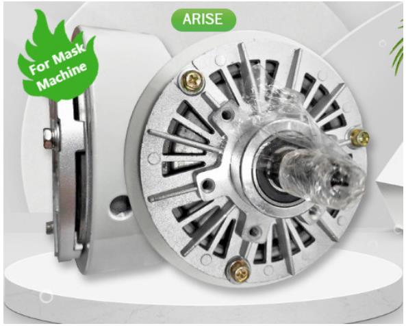
A magnetic powder brake is a friction brake employing electromagnetic principles to control torque or speed in rotating machinery. This article explores the structure and operation of magnetic powder brakes, their types, applications, maintenance, troubleshooting, and future development trends.
1. Structure of Magnetic Powder Brake:
A standard magnetic powder brake comprises two key components: the input rotor (field rotor) and the output rotor (armature rotor), separated by a small air gap. The driving shaft connects to the input rotor, and the load is attached to the output rotor.
2. Magnetic Powder Filling:
The space between the input and output rotors is filled with a thin magnetic powder suspended in a carrier fluid, often composed of iron or iron-based compounds. This powder facilitates torque transmission.
3. Electromagnetic Coil:
An electromagnetic coil surrounds the input rotor, generating a magnetic field when powered. The current passing through the coil creates a magnetic field in the air space between the two rotors.
4. Magnetic Particle Alignment:
The electromagnetic coil aligns iron particles in the magnetic powder with the field lines, creating bridges across the air gap, connecting the input and output rotors.
5. Torque Control:
Operators can control torque precisely by adjusting the input current to the electromagnetic coil. Increased current strengthens the magnetic field and transmitted torque, while decreased current weakens the magnetic field.
6. Torque Limitation:
Magnetic powder brakes offer the advantage of limiting maximum torque, preventing overloading or sudden torque spikes.
7. Slip and Speed Control:
These brakes can control slip and speed by adjusting the coil current, regulating the speed difference between the input and output rotors.
Types Of Magnetic Powder Brake:
Magnetic powder brakes are categorized into hysteresis and eddy current types, each with distinct operating principles related to ferromagnetic and conductive particles.
Wide Applications Of Magnetic Powder Brake:
Used in printing presses, wire drawing machines, web tension control systems, automotive and aerospace industries, and medical imaging equipment for MRI.
Maintenance And Troubleshooting Of Magnetic Powder Brake:
Maintenance:
Regular inspection for wear and damage.
Cleaning to eliminate dust and debris.
Lubrication with compatible lubricants.
Adjustments using a controller to regulate magnetic field intensity.
Troubleshooting:
Adjusting magnetic field strength.
Inspecting for worn or damaged components.
Reducing the load on the brake.
Development Trends of Magnetic Powder Brake:
Energy from Renewable Resources:
Control speed in wind turbines to optimize energy output and reduce wear.
Robotics:
Used for precise control of joint and limb movement in robotic systems.
Medical Science and Technology:
Provides adjustable resistance or support in medical devices like prosthetics and exoskeletons.
Aerospace:
Developing applications to control aircraft control surfaces, such as flaps and rudders.
Conclusion:
Understanding the structure, operation, and diverse applications of magnetic powder brakes is crucial for their effective utilization. As technological advancements continue, these brakes are expected to play a pivotal role in various industries, contributing to enhanced efficiency and control in rotational machinery.
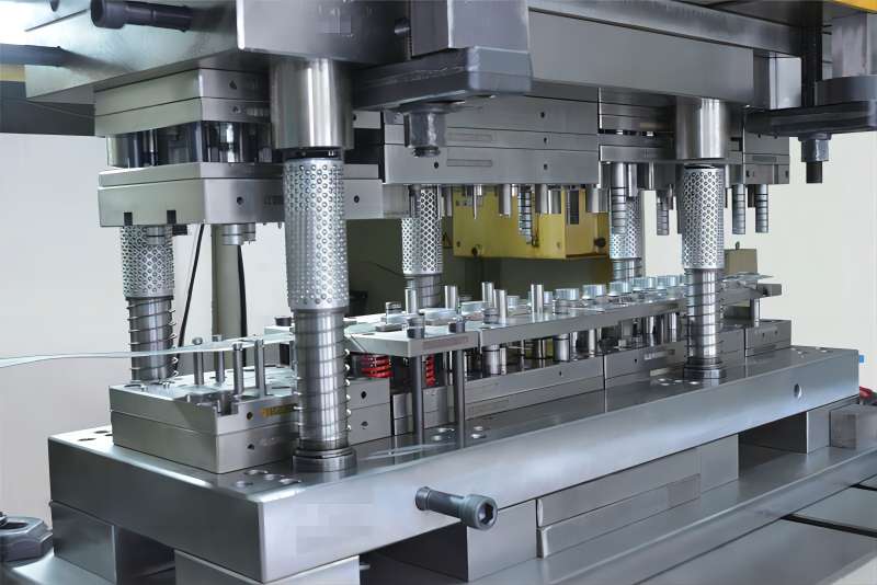
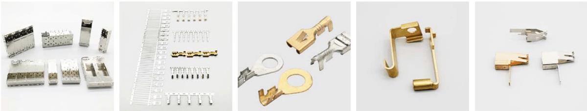
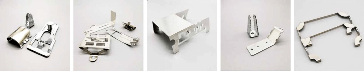
Metal stamping is a widely employed technique involving the deformation or cutting of various materials such as stainless steel, iron, copper, and aluminum, using punches and molds. This process is integral to numerous industries, including automotive, household appliances, and daily necessities. In the production of metal stamped parts, the frequent use of lubricating oil is essential, serving the critical purposes of reducing energy consumption and minimizing friction during the metal deformation process.
Why Use Lubricating Oil in Metal Stamping?
Energy Consumption Reduction:
For Stamping Parts: Lubricating oil minimizes direct contact between the mold and the deformed metal, facilitating relative sliding and shearing within the lubricating layer. This process significantly reduces friction and energy consumption during deformation.
For the Mold: The friction coefficient between the stamping material and the mold is decreased, enhancing the working conditions of the mold, protecting its surface, and prolonging its lifespan.
Surface Quality Improvement:
For Stamping Parts: Effective lubrication reduces external friction, preventing defects such as bonding, pressing, and scratches on the surface of the product. This anti-friction and anti-sticking effect enhances the overall quality of the stamped part.
Temperature Stability:
Lubricating oil forms a protective film on the surface of stamped parts during the process, mitigating the impact of temperature changes and preventing damage to the parts and dies.
Requirements for Lubricating Oil in Metal Stamping:
Heat Dissipation:
The lubricating oil should exhibit effective heat dissipation properties to handle temperature fluctuations during the stamping process.
Rust Resistance:
Good rust resistance is crucial to protect both the stamping parts and the associated tools and equipment.
Lubricity:
The oil must possess excellent lubricity to facilitate smooth sliding and shearing processes during metal deformation.
Non-corrosive and Non-toxic:
The lubricating oil should not corrode surfaces, produce toxic gases, and should be easy to clean, especially in welding parts.
How to Use Lubricating Oil in Metal Stamping:
Regular Cleaning:
Tools and containers for lubrication should be cleaned regularly to maintain cleanliness and efficiency.
Even Application:
Lubricating oil should be evenly applied using specialized tools like rollers or brushes.
Moderate Usage:
Apply lubricating oil in moderation to prevent wastage caused by excessive consumption.
In conclusion, the usage of lubricating oil in metal stamping is a critical aspect is a critical aspect of the production process, contributing to energy efficiency, surface quality improvement, and temperature stability. Manufacturers must adhere to specific requirements for lubricating oil and implement proper application methods to ensure the optimal performance of metal stamping operations. The diverse nature of metal stamping parts necessitates careful consideration of lubrication methods tailored to the unique characteristics of each product and production process.
In the intricate world of laboratory analysis, two stalwarts, the microplate reader and the spectrophotometer, reign supreme. These instruments share a common measurement principle, utilizing the Lambert-Beer law to measure sample absorbance. This article aims to shed light on differences between microplate reader and the spectrophotometer, focusing on three key aspects.

1. Major Differences
(1) Container for the Solution:
Microplate Reader:
Microplate readers utilize a plastic microplate, usually made of transparent polyethylene.
Each microplate can hold multiple solutions, often in 48 or 96 wells.
Requires a special photoelectric colorimeter due to unique requirements.
Spectrophotometer:
Employs a cuvette to contain the solution.
Each cuvette holds a single solution at a time.
Provides a straightforward container without additional solid-phase carrier properties.
(2) Direction of the Light Path:
Microplate Reader:
Features a vertical light path.
Light passes through the microplate vertically, either from top to bottom or vice versa.
The vertical light path minimizes the impact of liquid concentration or dilution.
Spectrophotometer:
Adopts a horizontal light path.
The light path remains constant regardless of the container's properties.
Affected by sample liquid level, microplate plate's light transmittance, and well bottom flatness.
(3) Length of the Optical Path:
Microplate Reader:
Vertical light path necessitates the length of the optical path to be the height of the liquid surface.
Measurement influenced by sample volume due to the unique path length.
Spectrophotometer:
Spectrophotometer adopts a fixed optical path length of 1 cm in the cuvette.
Ensures comparability across instruments and batches.

2. Advantages and Disadvantages Comparison
Spectrophotometer:
Advantages:
Wide detection wavelength range.
Consistent sample additions do not affect results.
Disadvantages:
Heavy workload, cumbersome operation, and time-consuming.
High reagent consumption.
Poor result stability, repeatability, and potential for large errors.
Difficulty in detecting and tracing substances.
Main Application Areas:
Qualitative and quantitative analysis in drug inspection, drug analysis, environmental testing, health, epidemic prevention, food, chemical industry, and scientific research.
Microplate Reader:
Advantages:
Processes a large number of samples simultaneously, saving time.
Requires fewer samples and reagents.
Simple operation, good repeatability, fast detection, and high efficiency.
Disadvantages:
96-well plate strong UV absorption below 300nm, limiting use for content determination.
Requires precise sample volume consistency, demanding skilled operation.
Main Application Areas:
Clinical testing, biological research, agricultural science, food, and environmental science.
In conclusion, understanding the distinctions between microplate readers and spectrophotometers is crucial for selecting the right tool for specific laboratory applications. Each instrument brings unique advantages and limitations, contributing to their diverse roles in scientific research and analysis.