Springs play a crucial role in various mechanical applications, utilizing the elasticity and structural properties of materials to achieve deformation and energy storage. This article explores the classification, parameters, and marking of springs, shedding light on their diverse applications in mechanical components.
Classification of Springs:
Springs come in various types, including coil spring, leaf spring, spiral spring, and disc spring. Among them, the cylindrical spiral spring stands out for its simple structure, convenient manufacturing process, and widespread applications. This type further divides into compression spring, extension spring, and torsion spring.
1.1 Compression Spring:
Characterized by large energy storage, low compression height, and stable stiffness, compression springs find applications in buffering, vibration reduction, energy storage, and controlling movement in mechanical equipment. They are commonly used in engine valve mechanisms, clutches, and automatic transmissions.
1.2 Extension Spring:
Similar to compression springs in performance and characteristics, extension springs are employed in situations requiring tensile load support, such as in overload safety devices of couplings.
1.3 Torsion Spring:
Primarily used for compression and energy storage, torsion springs serve as elastic links in transmission systems to withstand torsional loads. With linear characteristics, they are applied in dynamometers and forced air valve closing mechanisms.

Parameters of Springs:
Understanding the parameters of springs is essential for selecting the right type for specific applications.
2.1 Wire Diameter (d):
The diameter of the wire winding the spring.
2.2 Inner Diameter (D1), Outer Diameter (D2), and Pitch Diameter (D):
The inner diameter, outer diameter, and pitch diameter are crucial dimensions of the spring, where D is the average of D1 and D2.
2.3 Pitch of the Spring (t):
The axial distance between the section centerlines of two adjacent coils, excluding the support rings.
2.4 Number of Supporting Rings (nZ), Effective Number of Rings (n), and Total Number of Rings (n1):
To ensure uniform stress distribution, springs have supporting rings. The effective number of rings excludes support rings and is calculated as n = n1 - nZ.
2.5 Free Height (H0):
The height of the spring without any load.
2.6 Stretched Length of Spring Wire (L):
The length of the steel wire used for winding the spring.

Marking of Springs:
Properly marking springs is crucial for identification and application. The end coils can be either tightly ground (Type A) or tightly forged (Type B).
Example of Spring Marking:
YB 30x150x300 GB/T 2089-2003: Cylindrical spiral spring, wire diameter Φ30mm, pitch diameter Φ150mm, free height 300mm, manufacturing accuracy grade 3, material 60Si2MnA, surface painted, and can be left-handed or right-handed.
YA 1.2x8x40-2 GB/T 2089-2003: Cylindrical spiral spring, wire diameter Φ1.2mm, pitch diameter Φ8mm, free height 40mm, manufacturing accuracy class 2, material class B carbon spring steel wire, surface galvanized.
Summary:
This article provides an overview of spring classification, parameters, and marking. While standard springs are preferable for most design work, non-standard springs can be designed and customized under special circumstances to meet specific requirements. Understanding these aspects ensures the optimal selection and application of springs in various mechanical systems.
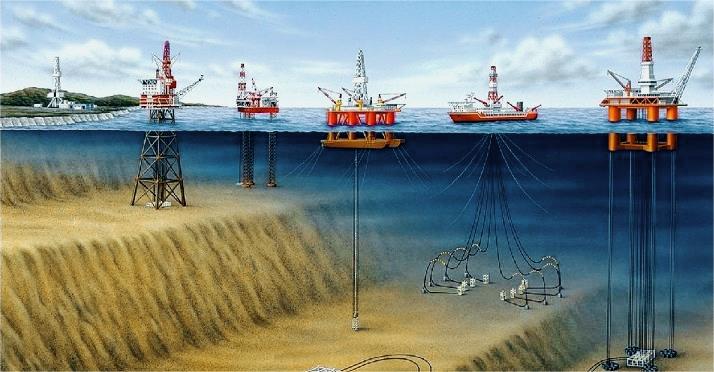
Oil rigs, imposing structures that dominate the sea's horizon, are renowned for their visible activities above the waterline. Yet, beneath the ocean's surface lies a lesser-known but equally intricate realm where essential oil rig operations unfold, extracting valuable resources concealed deep within the Earth's crust.
This article delves into the captivating world of oil rig underwater operations, exploring the equipment, challenges, and environmental considerations that make this aspect of the oil and gas industry both essential and distinctive. Additionally, we will discuss the crucial role that simulation plays in preparing workers for the complexities of these underwater operations.

Infrastructure for Oil Rig Underwater Operations
While the iconic structures of oil rigs command attention above water, a significant portion of operations occurs below the waterline. Subsea infrastructure, comprising pipelines, wells, and control systems, plays a pivotal role in extracting oil and gas from beneath the ocean floor.
Subsea Wells: Primary conduits for extracting hydrocarbons, equipped with components like blowout preventers (BOPs) to control well pressure and prevent blowouts.
Flowlines and Pipelines: Transport extracted oil and gas through a network of pipelines to the surface facility on the rig or to shore, designed to withstand harsh underwater conditions.
Control Systems: Complex, often remotely operated, systems that manage subsea infrastructure, monitoring well conditions, controlling valve operations, and providing critical data to surface operators.
Environmental Considerations of Oil Rig Underwater Operations
Oil rig underwater operations must adhere to strict environmental regulations to minimize their impact on marine ecosystems. Key considerations include:
Spill Response Plans: Comprehensive plans to address potential oil spills, including containment and cleanup strategies.
Marine Life Protection: Implementation of measures such as acoustic deterrent devices to minimize the impact of drilling and construction activities on marine mammals.
Sediment Management: Essential to prevent smothering of sensitive seabed ecosystems, with monitoring and control of sediment plumes.
Waste Disposal: Proper collection, treatment, and disposal of waste materials in accordance with environmental regulations.
Challenges for Oil Rig Underwater Operations
Operating beneath the sea presents unique challenges and complexities, requiring specialized expertise and equipment. Key challenges include:
Extreme Pressure: Subsea components must withstand extreme pressure conditions at great depths.
Corrosion and Erosion: Regular inspections and protective coatings are essential to combat the corrosive effects of seawater.
Remote Access: The inherently remote underwater environment requires specialized remotely operated vehicles (ROVs) for inspections, maintenance, and repairs.
Environmental Concerns: Stringent regulations and environmental impact assessments are in place to ensure responsible resource extraction.
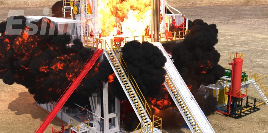
Importance of Simulation in Oil Rig Underwater Operations
Simulation plays a pivotal role in mitigating risks associated with oil rig underwater operations, contributing to safety, efficiency, and environmental sustainability:
Training and Skill Development: Workers undergo simulation-based training to familiarize themselves with subsea equipment, practice emergency response procedures, and gain proficiency in operating ROVs safely.
Equipment Testing and Validation: Simulation is instrumental in testing and fine-tuning subsea equipment and control systems, identifying and rectifying potential issues before field deployment.
Emergency Response Drills: Simulated emergency scenarios allow operators to refine response protocols and coordination, ensuring personnel are well-trained for actual emergencies.
Environmental Impact Assessment: Simulation tools assess the potential environmental impact, helping operators develop strategies to minimize ecological footprint and comply with regulations.
Conclusion
Oil rig underwater operations, a vital yet often overlooked facet of the oil and gas industry, demand specialized equipment, expertise, and commitment to environmental stewardship. As technology advances, these operations will continue playing a significant role in meeting the world's energy needs. Simulation serves as a cornerstone for safety, efficiency, and sustainability in this underwater frontier, allowing workers to practice scenarios, enhance decision-making skills, and familiarize themselves with the equipment and systems encountered during subsea operations.
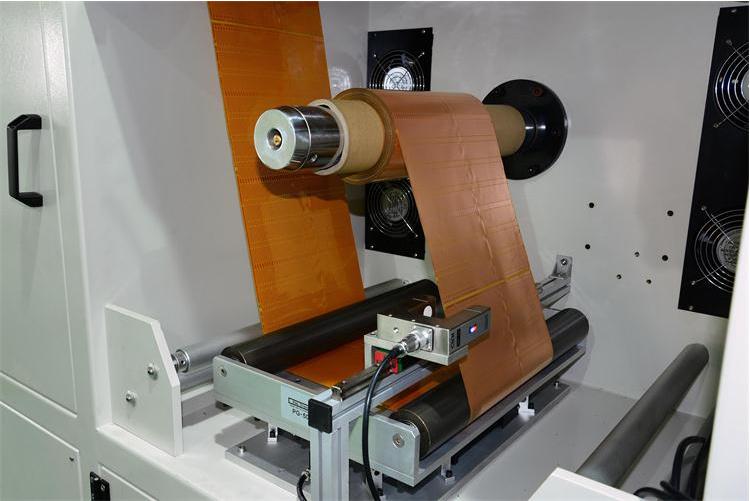
Web guiding systems play a crucial role in facilitating the seamless movement of materials through the manufacturing process in high-speed printing, where precision is of utmost importance. However, the accelerated pace of printing operations introduces new challenges that demand innovative solutions. This article explores the hurdles faced by web guiding systems in high-speed printing and delves into the solutions that pave the way for improved accuracy and efficiency.
Challenges in Web Guiding for High-Speed Printing
Dynamic Tension Variations
High-speed printing processes often lead to dynamic tension fluctuations in the web, impacting material alignment and registration.
Substrate Variability
Variations in printing substrates and materials, including differences in elasticity and thickness, make consistent web guiding at high speeds challenging.
Accurate Registration Requirements
Perfect color and element registration are essential when printing at high speeds, presenting a significant challenge in maintaining proper alignment throughout the process.
Web Flutter and Deflection
Increased speeds may cause the web to experience flutter or deflection, introducing deviations that must be swiftly detected and corrected by the web guiding system.
Vibration and Machine Dynamics
Vibrations and dynamic motions of high-speed printing equipment can influence the web's stability, complicating the challenge of keeping it aligned.
Material Stretch and Shrinkage
High speeds and associated forces can cause materials to stretch or shrink, impacting the accuracy of web guiding systems and necessitating real-time adjustments.
Solutions to Address Web Guiding Challenges in High-Speed Printing
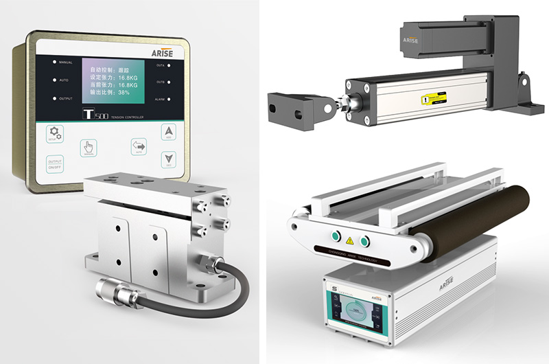
Advanced Sensor Technologies
Utilizing cutting-edge sensor technologies like ultrasonic or laser sensors enables real-time monitoring of web position and tension, allowing rapid adjustments to changes in material properties.
Closed-Loop Control Systems
Continuous analysis of sensor feedback by closed-loop control systems ensures real-time adjustments to the web guiding mechanism, maintaining precise alignment despite dynamic tension variations.
Smart Algorithms for Registration Control
Employing smart algorithms predicting and compensating for registration errors ensures accurate web alignment throughout the printing process, contributing to high-quality output.
Web Guiding Systems with Fast Response Times
Investing in systems with rapid response times ensures swift corrections, minimizing the impact of flutter, deflection, or sudden changes in web behavior.
Dynamic Tension Control Mechanisms
Incorporating tension control mechanisms that dynamically adjust to changes in web tension helps preserve stability, especially in settings where tension fluctuations are common.
Continuous Monitoring and Diagnostics
Implementing continuous monitoring and diagnostics through modern Human-Machine Interface (HMI) systems enables operators to identify potential issues before they affect print quality, reducing downtime.
Precision Rollers and Guiding Components
Upgrading precision-engineered rollers and web guiding components reduces friction, enhancing the overall stability of the system and mitigating the impact of vibrations and dynamic forces.
Material-specific Web Guiding Configurations
Tailoring configurations to the individual qualities of different substrates ensures the system can respond to variations in elasticity and thickness, resulting in improved performance.
Conclusion
Web guiding in high-speed printing is a delicate balance of precision and speed. Addressing the challenges posed by the rapid pace of modern printing requires the adoption of innovative technology, smart algorithms, and sensitive control systems. As the demand for high-quality, high-speed printing grows, the industry's ability to tackle these issues becomes increasingly crucial for achieving peak performance and producing flawless prints. By focusing on adaptable solutions and continuous innovation, web guiding systems can meet the challenges of high-speed printing with unparalleled accuracy and efficiency.
CNC machining is a sophisticated process involving various machine tools, materials, cutting tools, and methods. Drawing from extensive experience in actual production processes, we share valuable tips for optimizing CNC machining tools. These insights cover determining cutter points, selecting tool paths, and choosing the right CNC machining tools for different applications.
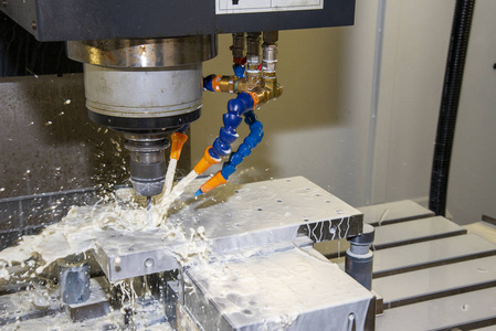
Tip 1: Determining Cutter Points in CNC Machining Tools
Set the cutter point on the part to be processed, ensuring it is a reference position or a finished point.
Establish a relative cutter point position with a fixed dimension relationship to the positioning reference.
Selection Principles:
Easy to find
Easy programming
Small cutter point error
Convenient inspection during processing
Set the origin position of the workpiece coordinate system based on the cutter point after clamping, ensuring consistency with the programming coordinate system.
Tip 2: Selecting Tool Paths in CNC Machining Tools
Consider the machining accuracy requirements of parts when determining the tool path.
Seek the shortest processing path to reduce empty tool time and improve efficiency.
Reduce the number of program segments.
Ensure continuous processing of the final contour using the last tool to maintain workpiece contour surface roughness.
Carefully consider the forward and backward path of the tool to minimize tool marks and avoid scratching the workpiece during vertical cutting.
Tip 3: Choosing CNC Machining Tools
Select a non-regrinding carbide end milling cutter for plane milling.
Use end milling cutters for rough milling and continuous cutting along the workpiece surface.
Utilize ball cutters and round cutters for curved surfaces and variable bevel profiles.
Adjust cutting parameters (cutting depth, spindle speed, and feed speed) based on the general principle of less cutting and fast feeding.
Conclusion:
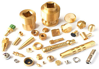
These tips, derived from years of CNC machining and surface finishing experience, aim to enhance the efficiency and precision of the process. At KENENG, we specialize in high-precision metal shell and precision hardware CNC cutting, offering a range of CNC processing services, including milling, turning, drilling, threading, tapping, EDM, wire EDM, custom finishing, prototyping, small batch production, and modification of existing parts. Our commitment to quality includes the use of high-precision measurement tools and advanced video equipment for inspections, ensuring only qualified products reach our customers. Choose KENENG for reliable CNC machining services and products tailored to your needs.
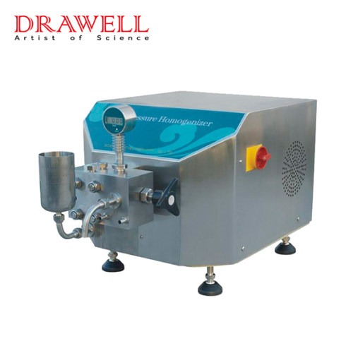
High-pressure homogenizers and microfluidizers play pivotal roles in the processing of emulsions, suspensions, and dispersions, aiming to reduce particle size and ensure a uniform particle distribution. Despite their common objective, these technologies differ in their mechanisms of action and applications. This article delves into the principles behind high-pressure homogenizers and microfluidizers and provides insights into choosing the appropriate instrument based on specific considerations.
High-Pressure Homogenizer Principle:
The high-pressure homogenizer operates by pressuring a fluid mixture through a narrow orifice after being pumped into a high-pressure chamber. This pressurization, typically achieved by a reciprocating pump, propels the fluid through a small orifice, generating intense shear forces and turbulence. This process effectively breaks down particles and droplets. As the fluid exits the orifice, a sudden pressure drop induces cavitation, further reducing particle size. The homogenized fluid is then collected for subsequent processing or immediate use.
Microfluidizer Principle:
Conversely, a microfluidizer utilizes a high-pressure pumping system to propel a fluid mixture through a microfluidic chamber equipped with precisely engineered channels and chambers. As the fluid traverses these channels, it experiences significant shear and cavitation forces, leading to particle size reduction and a more uniform product. The microfluidic chamber's design involves multiple intersecting channels that create microscale eddies and turbulence, enhancing fluid mixing and homogenization. The size and geometry of these channels can be customized to achieve specific mixing and homogenization effects, making the microfluidizer a versatile tool for particle size reduction and dispersion.
Factors for Choosing Between High-Pressure Homogenizer and Microfluidizer:
To make an informed choice between high-pressure homogenizers and microfluidizers, one must consider the following factors:
Performance:
High-pressure homogenizers are well-suited for larger-scale production requiring higher throughput.
Microfluidizers excel in smaller-scale production, offering precise control over particle size and distribution.
Maintenance and Safety:
Microfluidizers generally require less maintenance due to their simpler design and fewer moving parts.
Both devices involve high pressures and necessitate adherence to proper safety protocols during operation.

Cost:
High-pressure homogenizers are typically more cost-effective for large-scale production.
Microfluidizers may offer cost savings through reduced energy consumption, a smaller footprint, and minimized material waste due to precise particle size reduction.
Conclusion:
Choosing between high-pressure homogenizers and microfluidizers hinges on the specific application and production requirement. While both technologies share the goal of achieving uniform particle distribution, their differences in performance, maintenance, safety, and cost must be carefully weighed to select the optimal instrument that aligns with the user's needs.