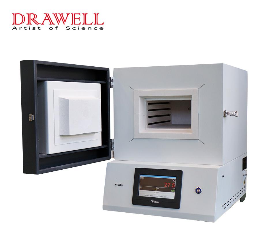
In laboratories and industrial environments, the muffle furnace stands as a stalwart tool for high-temperature applications. Whether it's heat-treating materials, conducting material testing, or executing ashing experiments, understanding the correct operation of a muffle furnace is paramount. This guide provides an in-depth walkthrough of utilizing a muffle furnace effectively, covering everything from setup procedures to temperature control and sample handling. By adhering to these steps, you can optimize the efficiency and safety of your experiments while ensuring precise and consistent results.
1. Safety Precautions:
Prioritize safety by donning appropriate personal protective equipment (PPE) such as heat-resistant gloves, goggles, and a lab coat.
Ensure the workspace is devoid of flammable materials and adequately ventilated.
Familiarize yourself with emergency shutdown procedures and the location of fire safety equipment.
2. Furnace Preparation:
Verify the power supply's integrity and ensure proper grounding.
Clean the muffle chamber meticulously, removing any debris or remnants of previous samples.
Confirm the secure insertion and closure of the muffle, the heating chamber, within the furnace.
3. Temperature Settings:
Refer to the operating manual specific to your muffle furnace model to comprehend its temperature control system intricacies.
Utilize temperature control knobs or digital displays to establish the desired temperature for your experiment.
Take note of any prescribed heating rates or ramping instructions pertinent to your application.
4. Sample Loading:
Prepare your sample meticulously in accordance with the experiment's specific requirements.
Employ suitable crucibles or containers capable of withstanding high temperatures.
Ensure precise positioning of the sample within the muffle chamber to facilitate accurate heating.
5. Furnace Closure:
Securely seal the muffle furnace upon loading the sample to prevent any heat loss.
Verify tight sealing of the furnace door to maintain optimal operational conditions.
6. Initiation of Heating Process:
Activate the muffle furnace by following the manufacturer's stipulated instructions upon turning on the power supply.
Witness the commencement of heat generation by the heating elements, initiating the furnace's ascent towards the set temperature.
7. Process Monitoring:
Keep vigilant watch over the temperature display or indicator throughout the heating phase.
Regularly assess the temperature within the muffle chamber to ensure its alignment with the desired parameters.
Exercise restraint in opening the furnace door unnecessarily to forestall heat dissipation and temperature fluctuations.
8. Cooling Down Phase:
Upon completion of the heating cycle, gradually decrease the furnace's temperature in accordance with your experimental prerequisites.
Permit the furnace to cool to a safe level before contemplating opening the door.
9. Sample Retrieval:
With due caution, carefully open the furnace door once the cooling process has sufficiently progressed.
Employ appropriate tools such as tongs or heat-resistant gloves to extract the sample from the muffle chamber, mindful of its potentially elevated temperature.
10. Cleaning and Maintenance:
Following the experiment's conclusion, undertake thorough cleaning of the muffle furnace to eliminate any residue or debris left behind by the sample.
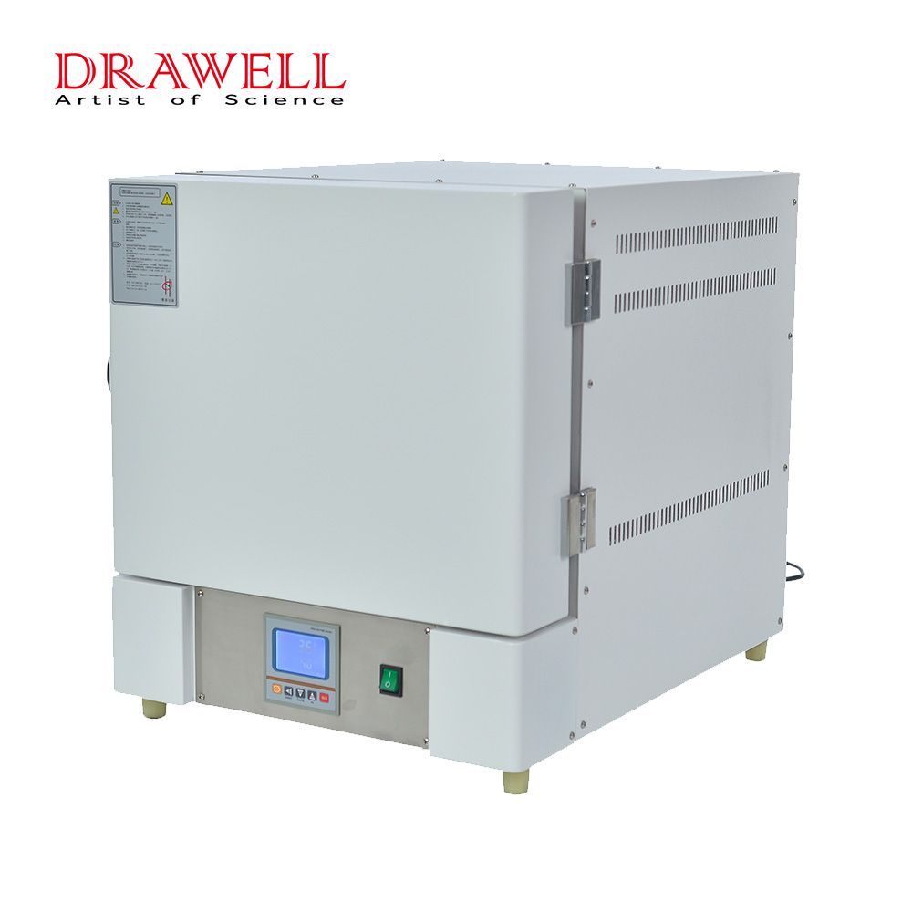
Adhere strictly to the manufacturer's guidelines delineating specific cleaning and maintenance procedures, thus ensuring the durable muffle furnace with long service life.
Conclusion:
In summary, proficiency in utilizing a muffle furnace is indispensable for conducting a myriad of high-temperature applications. By adhering meticulously to the steps outlined in this guide, you can ensure both the safe and efficient operation of your muffle furnace while upholding the integrity of your samples. Always prioritize safety precautions and consult the manufacturer's instructions pertinent to your furnace model. With consistent practice and adherence to proper techniques, you can wield the potency of a muffle furnace with confidence, accomplishing precise heat treatments, material tests, and other thermal processes adeptly.
Injection molding stands as a versatile manufacturing process, employed in crafting a plethora of products ranging from toys and consumer goods to intricate medical devices and automotive components. One pivotal aspect of this process lies in material selection, wielding a profound influence on the properties and performance of the final product. In this discourse, we delve into the nuances of selecting materials for injection molding products, encompassing the significance of material choice, the spectrum of materials utilized, and pivotal considerations in material selection.
Understanding Injection Molding:
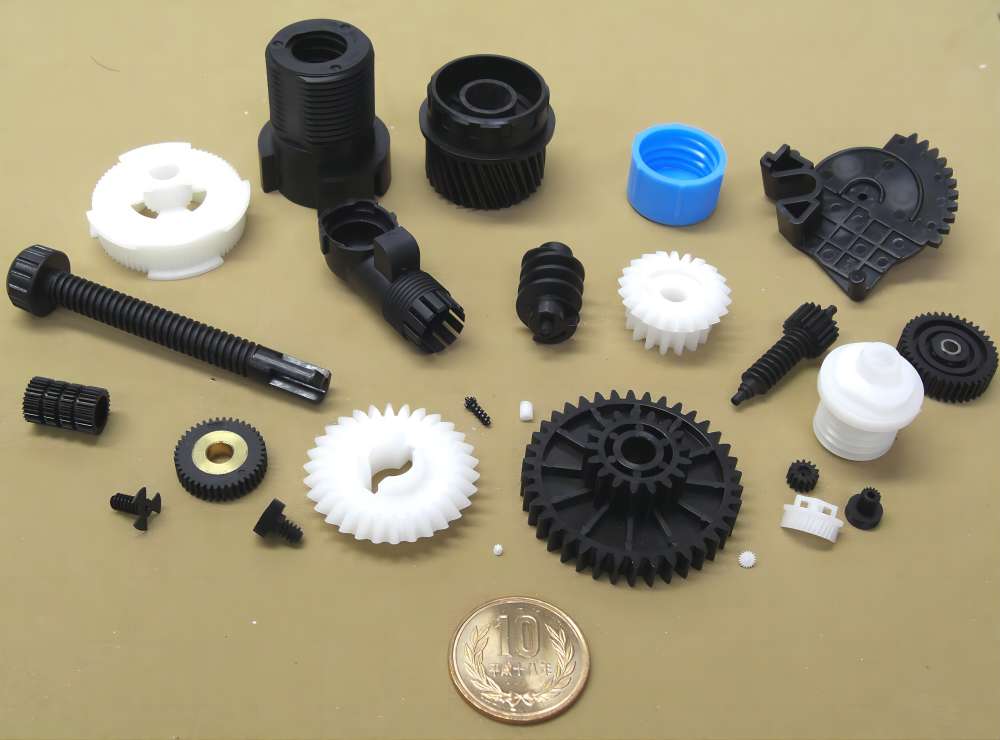
At its core, injection molding entails the heating of a thermoplastic to a molten state, followed by its injection into a mold. Subsequent cooling and opening of the mold culminate in the ejection of the finished product. This method facilitates the production of parts in high volumes, boasting intricate details and complex shapes, rendering it an ideal avenue for mass production endeavors.
Varieties of Materials for Injection Molding Products:
Material selection forms the bedrock of injection molding product design, wielding profound implications on performance, quality, and cost-effectiveness. Broadly, three main types of materials grace the domain of injection molding: thermoplastics, thermosetting plastics, and elastomers.
1. Thermoplastics:
Esteemed for their versatility, ease of processing, and recyclability, thermoplastics reign supreme in injection molding applications. Notable variants include polypropylene (PP), polyethylene (PE), polystyrene (PS), and polyvinyl chloride (PVC), each imbued with unique properties conducive to diverse applications.
2. Thermosetting Plastics:
Distinguished by their propensity to undergo a chemical reaction during the molding process, resulting in a cross-linked polymer structure impervious to melting or reshaping, thermosetting plastics epitomize durability and heat resistance. Epoxies, phenolics, and melamines stand as prime exemplars in this category, finding resonance in applications necessitating robustness.
3. Elastomers:
Exhibiting elastic properties conducive to stretching and subsequent reversion to their original form, elastomers find utility in applications mandating flexibility, cushioning, and impact resistance. Silicone and polyurethane emerge as quintessential players in the realm of injection molding elastomers.
Key Considerations in Material Selection:
The discerning process of material selection for injection molding products warrants a meticulous examination of various facets, including mechanical, chemical, and aesthetic properties, alongside judicious cost evaluations.
Mechanical Properties:
Encompassing factors like strength, durability, and flexibility, the mechanical attributes of a chosen material play a pivotal role in determining its performance under duress, ensuring functional integrity.
Chemical Properties:
Resilience to chemicals, UV radiation, and moisture constitutes a linchpin in enhancing the longevity and robustness of injection molded products, underscoring the significance of scrutinizing chemical properties during material selection.
Aesthetic Properties:
The visual allure and tactile appeal of a product are often predicated on factors like color, texture, and surface finish. Hence, meticulous attention to aesthetic properties during material selection can augment the product's marketability and consumer appeal.
Cost Considerations:
Balancing material costs against manufacturing expenses and product performance is indispensable in fostering cost-effective solutions, harmonizing economic viability with functional efficacy.
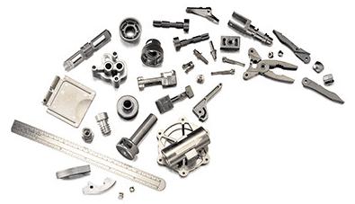
Specialized Endeavors: Metal Injection Molding (MIM):
Metal injection molding (MIM) emerges as a niche facet of injection molding, harnessing metal powders to fabricate high-density metal parts boasting intricate geometries. Widely prevalent in crafting medical devices, aerospace components, and electronics, MIM underscores the criticality of judicious material selection. Metals such as stainless steel, titanium, and tungsten feature prominently in MIM endeavors, delineating the trajectory of final product properties.
In Conclusion:
Material selection stands as a linchpin in the realm of injection molding, dictating the trajectory of product properties and performance. Thermoplastics, thermosetting plastics, and elastomers constitute the cornerstone of materials employed in this domain, each catering to distinct application requisites. Anchored by a holistic evaluation encompassing mechanical, chemical, aesthetic, and cost considerations, material selection emerges as a seminal determinant of injection molding product quality and market viability. By discerningly navigating the labyrinth of material choices, injection molding manufacturers can usher in a new epoch of excellence, crafting products tailored to meet the exigencies of diverse applications.
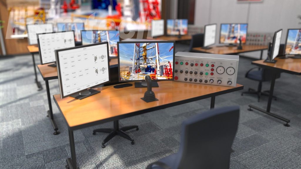
Oil drilling rigs serve as vital infrastructure for extracting hydrocarbons deep within the Earth's surface. These towering structures, positioned both onshore and offshore, represent remarkable feats of engineering and technology. This article delves into the world of oil drilling rigs, exploring their diverse types, functions, and transformative innovations that have shaped the industry.

Common Types of Oil Drilling Rigs
Onshore Rigs
Conventional Land Rigs: Versatile rigs used for vertical and deviated well drilling across various geological terrains.
Mobile Drilling Units: Portable rigs designed for rapid setup and dismantling, often utilized for exploratory drilling due to their mobility.
Jack-Up Rigs: Transportable offshore platforms with extendable legs, deployed in shallow waters for stability during drilling operations.
Semi-Submersible Rigs: Buoyant pontoons and columns that partially submerge, offering stability even in rough seas, commonly used in deepwater exploration.
Drillship Rigs: Self-propelled vessels equipped for drilling, featuring dynamic positioning systems for stability in deepwater and remote locations.

Tension Leg Platforms (TLPs): Floating platforms tethered to the seabed, providing stability while allowing vertical movement, ideal for deepwater drilling.
Functions of Oil Drilling Rigs
Exploration Drilling
Site Assessment: Initial appraisal of prospective drilling areas using geological data and seismic studies.
Wildcat Wells: Drilling test wells to assess the presence and potential quantity of hydrocarbons, crucial for identifying reserves.
Production Drilling
Production Wells: Creation of wells to extract oil and gas from confirmed reserves, the primary function of drilling rigs.
Appraisal Drilling: Assessment of reserve size and quality post-discovery, aiding in determining commercial viability.
Enhanced Oil Recovery (EOR) Drilling: Utilization of techniques like EOR to maximize production from mature fields.
Directional and Horizontal Drilling
Accessing reservoirs not directly beneath the drilling site, enhancing reservoir access and recovery.
Well Maintenance and Workovers
Ensuring wellbore integrity and retiring wells at the end of their productive life through plug and abandonment operations.
Noteworthy Innovations in Oil Drilling Rigs
Automation and Remote Monitoring
Integration of advanced control systems and sensors for real-time data collection and analysis, enhancing drilling accuracy and safety.
Top Drives
Motorized drilling systems providing rotational power, enabling faster and controlled drilling, particularly useful for complex tasks. The top drive simulators have been developed with the goal of training the functioning of the top drive device. It may provide training for all top drive operations as well as common accident handling. It can be utilized for driller/driller assistant, technician, and drilling team leader training. Trainees can master the operating method of top drive and the handling skills of common mishaps by training with the system.
Directional Drilling Technologies
Innovations like rotary steerable systems and measurement-while-drilling (MWD) equipment for accurate drilling of deviated and horizontal wells.
Digital Twin Technology
Creation of virtual models replicating physical rigs, allowing for simulation and optimization of drilling processes, enhancing safety and efficiency.
Dual Gradient Drilling (DGD) Systems
Techniques controlling drilling fluid density for consistent well pressure, reducing the risk of blowouts and environmental incidents.
Enhanced Drilling Fluids
Development of environmentally friendly drilling fluids enhancing lubrication, temperature stability, and wellbore stability for safer and sustainable drilling.
Wellbore Monitoring and Control Systems
Advanced systems continuously monitoring downhole conditions and improving drilling parameters using real-time data, enhancing accuracy and safety.
Conclusion
Oil drilling rigs are indispensable for the exploration and production of hydrocarbon resources, performing diverse functions across various terrains. Recent innovations have made drilling operations safer, more efficient, and environmentally friendly, ensuring a sustainable energy future. These rigs remain at the forefront of technological advancement, unlocking new reserves and driving the energy industry forward.
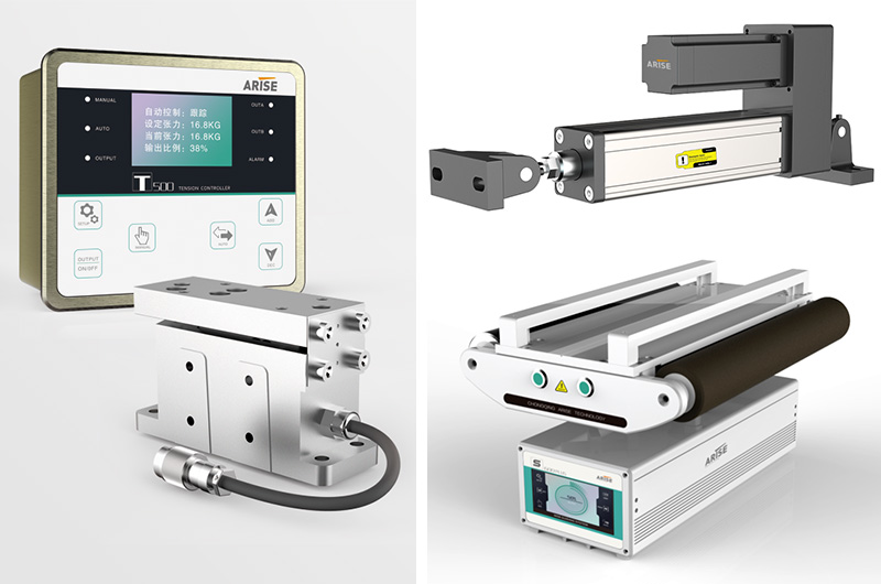
Precision and accuracy play pivotal roles in industrial manufacturing, particularly in operations involving continuous webs of materials like paper, film, or foil. Even minuscule variations can lead to costly faults and production delays. To ensure seamless operations and high-quality outputs, regular maintenance and calibration of web guiding systems are indispensable. In this article, we delve into the significance of maintenance and calibration practices in maximizing the efficiency and reliability of web guiding systems.
Regular Maintenance Practices in Web Guiding Systems
Cleaning and Inspection: Regular cleaning and inspection are essential maintenance procedures for web guiding systems. Removing debris, dust, and residue from guiding rollers and sensors ensures smooth operation and longevity. Visual evaluation for wear, damage, or misalignment is crucial to preempt potential issues.
Lubrication: Proper lubrication of moving parts minimizes friction, wear, and ensures smooth functioning. Following manufacturer recommendations for lubrication type and frequency is paramount to extend component life and maximize system operation.
Tension Adjustment: Maintaining proper web tension is vital to prevent wrinkles, creases, and breaks. Regularly checking and adjusting tension settings ensures consistent tension levels across the web, enhancing product quality and process efficiency.
Alignment Verification: Regularly verifying the alignment of guiding rollers and sensors guarantees precise web guidance. Proper alignment reduces edge deviations and maintains product quality. Utilizing alignment tools and techniques ensures accuracy.
Software Updates: Staying updated with the latest software releases provided by the manufacturer enhances system functionality and reliability. Prompt installation of updates ensures compatibility with other equipment and processes, benefiting from performance enhancements and bug fixes.

Calibration Practices in Web Guiding Systems
Sensor Alignment: Accurate sensor alignment is crucial for reliable web position detection. Ensuring sensors are perpendicular to the web path and aligned with the desired tracking position optimizes detection accuracy along the entire web width.
Tension Calibration: Proper tension calibration maintains consistent tension levels, minimizing faults and material waste. Monitoring tension levels and adjusting control systems according to production requirements and material properties is essential.
Position Control Adjustment: Calibrating position control settings minimizes edge deviations and maintains correct web alignment. Fine-tuning settings like gain, offset, and response time optimizes alignment accuracy.
Sensor Sensitivity Optimization: Optimizing sensor sensitivity ensures reliable detection of web deviations. Adjusting sensitivity settings based on material characteristics and environmental conditions enhances detection accuracy, even at low contrast or speed variations.
Verification and Validation: After calibration adjustments, conducting test runs using representative materials and conditions verifies system performance. Comparing actual performance against specified tolerances and making further adjustments ensures accuracy and reliability.
Documentation and Record-Keeping: Maintaining thorough records of calibration activities facilitates traceability and responsibility. Documenting calibration dates, adjustments, and test results aids in troubleshooting and continuous improvement efforts.
Conclusion
Regular maintenance and calibration are indispensable practices for ensuring the reliable web guiding systems with optimal performance. By following proactive maintenance schedules, conducting thorough inspections, and calibrating system parameters as needed, manufacturers can reduce downtime, eliminate defects, and increase production efficiency.
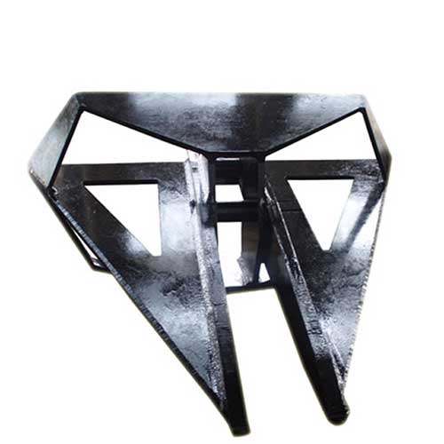
Energy efficiency is a crucial consideration in the design of high holding power anchors, particularly in industries like maritime and offshore, where these anchors play a pivotal role in vessel stability and safety. Recent advancements in anchor design not only enhance their holding power but also significantly improve energy efficiency in marine operations. This article delves into the latest innovations in high holding power anchor design and their impact on energy conservation and sustainability.

Enhanced Shapes:
Modern anchor designs integrate aerodynamic and hydrodynamic principles to minimize drag during deployment and usage. By reducing resistance in water, less energy is needed to maintain the anchor's position, especially in dynamic conditions with strong currents or waves. Computational fluid dynamics (CFD) simulations refine anchor shapes, resulting in lower energy consumption during deployment and retrieval.
Material Advancements:
Innovations in materials science have led to the development of high-strength, lightweight materials that are durable and corrosion-resistant. These materials reduce the anchor's weight, requiring less energy for handling, deployment, and retrieval. Moreover, advanced coatings and surface treatments minimize friction and corrosion, further enhancing energy efficiency.
Optimized Fluke Design:
Improvements in anchor fluke design, including shape, angle, and surface area, enhance penetration into different seabeds more efficiently. Better penetration means increased holding power with less weight and drag, resulting in energy savings. Some anchors incorporate mechanisms like roll-bars or setting flukes to aid in quick and secure penetration of the seabed.
Smart Anchor Systems:
Integration of sensors, actuators, and real-time monitoring systems enables dynamic adjustments based on environmental conditions. Smart anchors autonomously optimize their orientation and position, conserving energy while ensuring secure anchoring. These systems offer valuable insights into anchor performance, facilitating informed decisions to further enhance energy efficiency.
Hybrid Energy Integration:
High holding power anchors are increasingly used alongside renewable energy systems such as offshore wind turbines or tidal energy converters. Anchor designs accommodating these systems improve overall efficiency in renewable energy generation by ensuring stable and reliable mooring with minimal energy loss. Optimizing anchor design for renewable energy systems maximizes energy efficiency and sustainability.
Innovative Deployment Mechanisms:
Advancements in anchor deployment mechanisms, such as remotely operated systems or autonomous underwater vehicles (AUVs), enable precise positioning with minimal human intervention and energy expenditure.
Advanced Testing and Simulation:
Engineers utilize computer-aided design (CAD), computational fluid dynamics (CFD), and finite element analysis (FEA) to virtually optimize anchor designs before physical prototyping. This iterative design approach eliminates the need for costly and energy-intensive trial and error testing, resulting in more efficient anchor designs.
Integration with Renewable Energy:
In some instances, high holding power anchors are paired with renewable energy systems like offshore wind turbines or tidal energy devices. Aligning anchor design with these systems boosts overall energy efficiency in marine renewable energy applications.
In conclusion, advancements in high holding power anchor design not only enhance maritime safety and reliability but also contribute significantly to energy efficiency and sustainability. As technology progresses, further innovations in anchor design are anticipated to drive even greater improvements in energy efficiency and sustainability for the maritime and offshore sectors.