Horizontal oil drilling, a groundbreaking innovation in the oil and gas industry, has transformed how hydrocarbon resources are accessed and produced. Vertical drilling was once the standard, but horizontal drilling has opened up new opportunities by allowing operators to access previously unreachable reserves. In this article, we will explore the process, advantages, challenges, environmental considerations, and the vital role of simulation technology associated with horizontal oil drilling.

Process of Horizontal Oil Drilling
Horizontal drilling, also known as directional drilling, is the process of drilling a wellbore at an angle to access oil or gas reservoirs beneath the Earth's surface. Unlike traditional vertical drilling, horizontal drilling involves both vertical and horizontal drilling. The procedure can be summed up as follows:
Vertical Drilling: A wellbore is initially drilled vertically from the surface to a certain depth.
Build Section: At a specific depth, the drilling direction is changed, and the wellbore is curved to create a "build section".
Horizontal Drilling: After the curve, the wellbore continues horizontally through the oil or gas reservoir.
Well Completion: Once the desired length of the horizontal section is achieved, the well is completed with casing and cement to allow for production.
Advantages of Horizontal Oil Drilling
Increased Reservoir Access: Horizontal drilling enables operators to access reservoirs that would otherwise be unreachable via typical vertical drilling, increasing the amount of oil and gas that can be recovered.
Enhanced Recovery Rates: A well’s horizontal portion provides more contact with the reservoir, resulting in higher recovery rates.
Reduced Environmental Impact: Operators can reduce surface footprint and environmental damage by accessing reservoirs from a single drilling location.
Improved Well Economics: Higher recovery rates and lower drilling costs make horizontal drilling commercially appealing.
Enhanced Well Control: Controlling the trajectory of a well allows operators to avoid geological complications and potential drilling issues.

Challenges and Environmental Considerations Faced by Horizontal Oil Drilling
While horizontal drilling offers numerous advantages, it also presents unique challenges and considerations.
Challenges:
Technical Complexity: Horizontal drilling is more technically difficult than vertical drilling, necessitating sophisticated equipment and skill.
Increased Costs: Horizontal drilling technology and expertise can result in higher initial expenses.
Regulatory Compliance: Operators must adhere to strict regulations to ensure safe and environmentally responsible drilling.
Wellbore Integrity: Maintaining wellbore integrity is critical to prevent accidents and ensure the well’s long-term productivity.
Environmental Considerations:
Reduced Surface Impact: Horizontal drilling minimizes surface disruption, which is especially beneficial in ecologically sensitive areas.
Risk of Contamination: The potential for groundwater contamination from drilling fluids and hydrocarbon migration must be carefully managed.
Spill Prevention: Comprehensive spill prevention and response plans are essential to address potential environmental risks.
Habitat Protection: Operators must consider the impact on local wildlife habitats and ecosystems.
Regulatory Compliance: Strict adherence to environmental regulations and best practices is essential to mitigate environmental impact.
Important Role of Simulation Technology in Horizontal Oil Drilling
The use of simulation in the design and execution of horizontal drilling projects is critical. It provides engineers and drillers with the knowledge and tools needed to make informed decisions and optimize the drilling process.
Geosteering:
Geologists and geosteerers use simulation software to construct 3D models of the subsurface, allowing them to see rock formations and potential obstructions. By continuously updating the model in real-time using data from downhole sensors, geosteerers can precisely guide the drill bit within the reservoir.
Drilling Trajectory Planning:
Drilling and well simulation systems aid in designing the optimal well path by considering geological data, wellbore stability, and reservoir parameters. This enables engineers to plot the most efficient path, minimizing the chances of getting stuck or veering off course.
Wellbore Stability Analysis:
Oil simulation software predicts the mechanical behavior of the wellbore and drill string. It evaluates the stresses and pressures acting on the wellbore walls and forecasts the likelihood of issues such as wellbore collapse or fluid ingress. This data informs the selection of drilling parameters and the design of the drilling assembly.
Real-time Monitoring and Adjustments:
During the drilling process, data from downhole sensors and measurements are fed into the simulation software. This real-time feedback allows drillers to make immediate adjustments to the drilling parameters, ensuring the drill bit remains within the target zone.
Benefits of Simulation in Horizontal Drilling:
Precision and Accuracy: Simulation provides a high level of precision in wellbore placement, helping minimize deviation from the target zone and ensuring the well intercepts the most productive areas of the reservoir.
Enhanced Efficiency: By optimizing wellbore trajectories and parameters, drilling and well control simulation reduces drilling time and operational costs, and minimizes the risk of complications that can lead to costly delays.
Risk Mitigation: Simulation helps identify potential drilling challenges in advance, allowing for proactive risk management and wellbore stability assurance.
Improved Recovery Rates: Accurate well placement in the reservoir maximizes hydrocarbon recovery, leading to higher production rates and increased profitability.
Safety and Environmental Protection: Simulation helps prevent issues like wellbore instability, fluid influx, or well collisions, which can pose safety risks and environmental concerns.

Conclusion
Horizontal oil drilling has revolutionized the oil and gas industry by allowing access to previously undiscovered sources and increasing recovery rates. Oil and gas simulation ensures that horizontal drilling operations are optimized for maximum hydrocarbon recovery by accurately simulating well trajectories, analyzing wellbore stability, and providing real-time guidance. As technology and industry practices continue to evolve, horizontal drilling will play a critical role in ensuring a sustainable and efficient future for the oil and gas sector, meeting the world’s energy demands while safeguarding the environment.
The in-line width measurement system represents a significant advancement in manufacturing technology, offering real-time precision measurement capabilities that enhance product quality, increase efficiency, and reduce waste. This system is particularly crucial in industries where the accurate width of materials is critical to the performance and functionality of the final product.

Understanding the In-line Width Measurement System
The in-line width measurement system is a sophisticated technological solution designed to accurately measure the width of materials as they move along the production line. Unlike traditional measurement methods that rely on manual inspection or periodic sampling, the in-line system provides real-time data, allowing for immediate adjustments and corrections to ensure consistent product quality.
At its core, the in-line width measurement system typically consists of precision sensors, cameras, lasers, or other measurement devices strategically positioned along the production line. These sensors continuously monitor the width of the material as it passes through, capturing data with exceptional accuracy and reliability.
Key Components and Functionality of the In-line Width Measurement System
Precision Sensors
Role: Precision sensors are at the forefront of the in-line width measurement system, responsible for capturing detailed measurements of the material’s width in real-time.
Functionality: These sensors employ various technologies such as lasers, cameras, ultrasonic waves, or optical sensors to accurately measure the width of the material passing through the production line.
Placement: Sensors are strategically positioned along the production line to cover the entire width of the material, ensuring comprehensive and precise measurement coverage.
Data Processing Unit
Role: The data processing unit acts as the brain of the system, processing the measurement data collected by the sensors and performing complex calculations to determine the material width accurately.
Functionality: Using advanced algorithms, the data processing unit analyzes the raw measurement data, filters out noise, compensates for environmental factors, and calculates the precise width of the material.
Real-time Processing: The unit operates in real-time, enabling instantaneous adjustments to the production process based on the width measurement data.
Control System
Role: The control system receives the processed width measurement data from the data processing unit and implements necessary adjustments to maintain the material within the specified width tolerances.
Functionality: Depending on the production line setup and requirements, the control system can control various parameters such as conveyor speed, machine settings, tension levels, or other relevant factors to ensure consistent material width.
Closed-loop Control: The control system operates in a closed-loop manner, continuously receiving feedback from the sensors and making rapid adjustments to maintain optimal production conditions.
Feedback Mechanism
Role: The feedback mechanism provides essential information to operators and supervisors, allowing them to monitor production performance and intervene if deviations from the specified width tolerances occur.
Functionality: Real-time feedback alerts operators to any width-related issues, enabling prompt corrective actions to prevent quality defects or production disruptions.
Visualization Tools: Feedback mechanisms often include visualization tools such as graphical displays or data logging systems, allowing operators to track width measurements over time and identify trends or anomalies.
Integration Interfaces
Role: Integration interfaces facilitate seamless communication and integration of the in-line width measurement system with other components of the production line, such as PLCs (Programmable Logic Controllers), SCADA (Supervisory Control and Data Acquisition) systems, or MES (Manufacturing Execution Systems).
Functionality: Integration interfaces ensure interoperability between the width measurement system and existing production line infrastructure, enabling centralized control, data sharing, and synchronization of operations.
Compatibility: These interfaces may support industry-standard communication protocols such as OPC (OLE for Process Control) or Modbus, ensuring compatibility with a wide range of industrial automation systems.
Benefits of the In-line Width Measurement System
Enhanced Product Quality: By providing real-time measurements of material width, the system ensures consistent product dimensions within tight tolerances, resulting in higher-quality products that meet or exceed customer expectations.
Improved Efficiency: Real-time monitoring and adjustments optimize production processes, reducing material waste and minimizing downtime associated with manual inspections or adjustments. Increased efficiency leads to higher throughput and lower production costs.
Cost Savings: The system helps minimize scrap, rework, and material usage by detecting deviations from specified width tolerances early in the production process. This translates into significant cost savings over time, improving the overall profitability of manufacturing operations.
Reduced Rework and Waste: By detecting width variations in real-time, the system enables immediate corrective actions to be taken, reducing the need for rework and minimizing material waste. This contributes to a more sustainable manufacturing environment.
Increased Flexibility and Adaptability: The system can be easily integrated into existing production lines and configured to accommodate different materials, widths, and production requirements. This flexibility enables manufacturers to adapt quickly to changing market demands and production conditions.
Enhanced Process Control: Continuous monitoring of material width allows for precise control of production parameters such as machine settings, conveyor speeds, and tension levels. This results in tighter process control and greater consistency in product quality.
Compliance and Traceability: The system provides comprehensive documentation of width measurements, enabling manufacturers to demonstrate compliance with regulatory standards and quality requirements. This enhances traceability and facilitates quality assurance processes.
Applications of the In-line Width Measurement System
Textiles and Fabrics: In textile manufacturing, maintaining consistent fabric width is essential for ensuring uniformity in finished products such as clothing, upholstery, and linens. The in-line measurement system ensures that fabric rolls maintain the desired width throughout the production process, minimizing variations and defects.
Paper and Packaging: In paper mills and packaging facilities, accurate width measurement is crucial for producing rolls of paper, cardboard, and packaging materials that meet customer specifications. The system helps control the width of these materials, ensuring they are within tolerance limits and suitable for further processing or packaging.
Plastics and Films: In the plastics industry, maintaining precise width dimensions is vital for producing films, sheets, and extruded products used in packaging, construction, and other applications. The in-line width measurement system ensures that plastic materials are extruded or processed to the correct width, preventing defects and optimizing material usage.
Metal Processing: In metal processing facilities, maintaining consistent width dimensions is essential for producing metal strips, sheets, and coils used in various industries such as automotive, construction, and manufacturing. The system helps monitor and control the width of metal materials during rolling, cutting, or stamping processes, ensuring they meet tight tolerances.
Converting and Printing: In converting and printing operations, precise width measurement is crucial for ensuring accurate registration and alignment of printed materials, labels, and packaging. The in-line width measurement system helps maintain the correct width of substrates and printed materials, minimizing waste and improving print quality.
Flexible Electronics: In the production of flexible electronics such as displays, sensors, and printed circuits, maintaining uniform material width is essential for ensuring device performance and reliability. The system enables manufacturers to monitor and control the width of flexible substrates and conductive materials during the manufacturing process, optimizing yield and quality.
Medical Devices and Pharmaceuticals: In the medical device and pharmaceutical industries, precise width measurement is critical for producing components such as films, tapes, and packaging materials used in medical devices and drug delivery systems. The in-line width measurement system ensures that these materials meet stringent quality standards and regulatory requirements, ensuring patient safety and product integrity.
Food and Beverage Packaging: In food and beverage packaging facilities, accurate width measurement is essential for producing packaging materials such as films, pouches, and labels that protect and preserve food products. The system helps maintain the correct width of packaging materials, ensuring they meet hygiene standards and regulatory requirements while minimizing packaging waste.
Conclusion
In an era where precision and efficiency are paramount, the in-line width measurement system stands out as a game-changer in manufacturing. By providing real-time measurement data and enabling immediate adjustments, this innovative technology helps industries maintain the highest standards of quality while optimizing production processes.
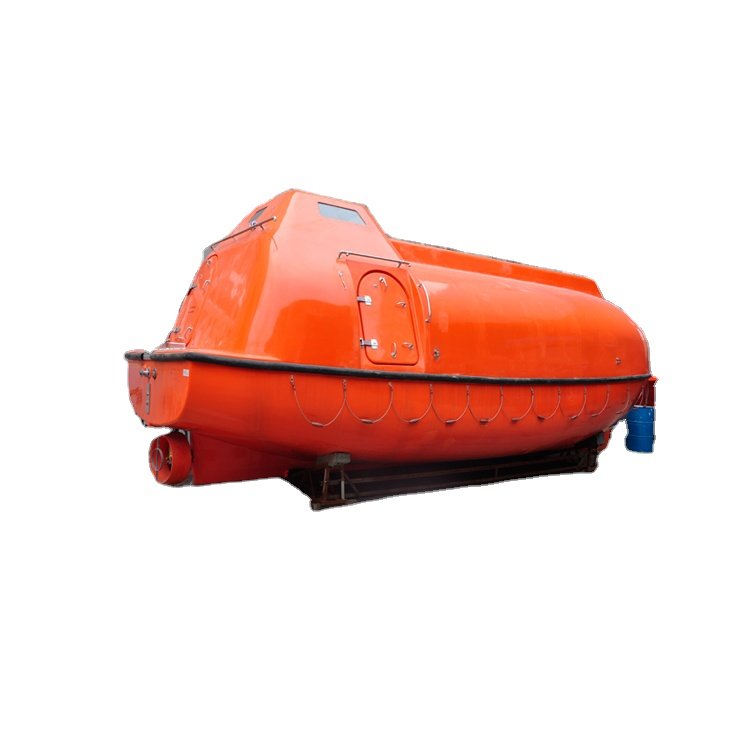
Lifeboats are essential safety features on vessels, designed to provide a means of escape and survival in emergencies. Ensuring marine lifeboats are in optimal condition requires rigorous and regular maintenance and inspection. Proper upkeep not only meets international safety standards but also ensures the safety of crew members when needed.
Key Components of Marine Lifeboat Maintenance
Hull and Structure
Inspection for Damage: Regularly check the hull for cracks, corrosion, or structural damage.
Cleaning and Painting: Clean the hull to remove salt and debris, and ensure it is painted to prevent corrosion.v
Launching Mechanisms
Davits and Winches: Inspect davits and winches for wear and tear, lubricate moving parts, and ensure proper operation.
Ropes and Cables: Check for fraying, corrosion, or damage and replace as necessary.
Engines and Propulsion
Engine Checks: Perform routine maintenance, including oil changes, fuel filter replacements, and inspection of belts and hoses.
Propellers and Shafts: Inspect and maintain to ensure they are free of obstructions and damage.
Safety Equipment
Life Jackets and Lifebuoys: Ensure they are in good condition and easily accessible.
Emergency Rations and Water: Inspect and replace life saving equipmentbefore expiration dates.
Communication and Navigation
Radio and Signaling Equipment: Test to ensure full functionality.
Navigational Aids: Verify the condition of compasses and lights.
Seating and Safety Belts
Seat Integrity: Check for structural integrity and comfort.
Safety Belts: Ensure they are operational and in good condition.
Inspection Protocols and Procedures
Pre-Inspection Preparation
Documentation Review: Review previous reports and maintenance records to identify recurring issues.
Safety Briefing: Conduct a safety briefing for the inspection team.
Visual Inspection
Exterior and Interior: Perform a thorough visual inspection, noting any damage or irregularities.
Component Check: Examine the hull, engine, safety equipment, and launching mechanisms.
Functional Testing
Engine Start-Up: Test the engine for smooth operation.
Launch Test: Simulate a launch to verify the proper functioning of davits, winches, and release mechanisms.
Detailed Reporting
Inspection Report: Document findings in a detailed report, noting any issues requiring attention.
Maintenance Log: Update the log with actions taken and parts replaced or repaired.
Challenges and Solutions in Marine Lifeboat Maintenance
Harsh Marine Environment
Problem: Exposure to saltwater, humidity, and temperature extremes causes corrosion and damage.
Solution: Apply specialized marine-grade paints and coatings, implement routine cleaning, and use marine-grade materials.
Limited Access and Space
Problem: Lifeboats are often stowed in confined spaces, making access difficult.
Solution: Use compact tools and modular components, and schedule maintenance during downtime.
Regulatory Compliance
Problem: Keeping up with evolving safety regulations is challenging.
Solution: Provide continuous training, use digital systems for documentation, and conduct external audits.
Wear and Tear
Problem: Frequent use can lead to accelerated wear and tear.
Solution: Perform routine inspections, use high-quality parts, and establish a rigorous maintenance schedule.
Complex Systems and Technology
Problem: Advanced technologies require specialized knowledge for maintenance and repair.
Solution: Provide specialized training, collaborate with manufacturers for support, and maintain up-to-date manuals.
Human Error
Problem: Human error can lead to overlooked issues or improper repairs.
Solution: Develop standardized procedures, use checklists and protocols, and establish a quality control system.
Limited Availability of Spare Parts
Problem: Obtaining spare parts, especially in remote locations, can be challenging.
Solution: Maintain an inventory of critical spare parts, develop strong supplier relationships, and standardize parts across the fleet.

Future Innovations for Maintenance and Inspection
Advanced Monitoring Systems
Smart Sensors: Monitor real-time performance metrics and analyze data for predictive maintenance.
Remote Monitoring and Diagnostics
IoT and Connectivity: Enable remote monitoring and diagnostics using cloud-based solutions.
Autonomous Inspection Technologies
UAVs: Use drones for aerial inspections of hard-to-reach areas.
Robotics and Automation
Underwater Inspections: Develop robotic systems for underwater inspections and automate routine tasks.
Predictive Maintenance Algorithms
AI and Machine Learning: Analyze historical data to predict maintenance needs and shift to condition-based maintenance.
AR and VR for Training and Maintenance Support
AR Applications: Use AR for maintenance guidance and training.
VR Simulations: Provide VR simulations for crew training in emergency procedures.
Advanced Materials and Coatings
Nano-coatings: Use advanced materials to enhance resistance to corrosion and wear.
Integrated Maintenance Management Systems
Digital Platforms: Implement systems for lifecycle management, including maintenance scheduling and regulatory compliance.
Conclusion
Regular and thorough maintenance and inspection of marine lifeboats are vital for maritime safety. Adhering to structured protocols and best practices ensures compliance with safety regulations and enhances the reliability and longevity of lifeboats, safeguarding the lives of crew members in emergencies.
In various aspects of production and daily life, bolt connections often include a washer. However, the necessity and purpose of washers in these connections can sometimes be unclear. This article explores the design of bolt connections and discusses when and why washers are used.
When Flat Washers are Necessary for Bolt Connections
Flat washers play a significant role in fastening systems, offering various benefits and being employed in several scenarios to achieve specific outcomes.
1. Surface Protection during Frequent Disassembly
Flat washers are used to protect the surfaces of connected components during frequent disassembly. By placing a flat washer at the position of the nut or bolt head, the risk of surface damage is mitigated, particularly for precision-machined surfaces.

2. Meeting Friction Coefficient Requirements
In some cases, flat washers are used to meet precise friction coefficient requirements without separate testing. For instance, wind turbine bolt connections often use combination washers. In such situations, all components, including bolts, nuts, and washers, are provided by the same manufacturer, ensuring consistent friction coefficients between the nuts and washers. The supplier must also test and ensure that the torque coefficients meet technical requirements.
3. Reducing Pressure on Connected Components
When bolt strength is relatively high and the allowable stress in connected components is low, flat washers are essential. This is particularly relevant in the context of the growing demand for lightweight automotive structures. By adding flat washers, the pressure on the bearing surfaces of connected components is reduced, preventing yielding and permanent plastic deformation.
4. Pressure Distribution and Sealing
Flat washers are valuable when pressure distribution and sealing are required. Increasing the washer size enlarges the stress distribution diameter and ensures effective sealing between connected surfaces. This is crucial in applications where airtight or watertight seals are necessary.
5. Compensating for Positional Tolerance Deviations
In automotive manufacturing, where stamping and welding processes are prevalent, the positional tolerance of holes may not align perfectly. In such cases, larger hole diameters are used, and flat washers are added to compensate for positional tolerance deviations. This ensures proper alignment and a secure connection.
6. Ease of Installation Adjustment
For ease of installation adjustment, long holes are sometimes created in control arm brackets or control tables. In such instances, thick flat washers or specialized washers may be used to allow for adjustments within a certain range.
Why Spring Washers are Used for Anti-Loosening
spring washers also known as lock washers, are primarily employed to increase the friction force between nuts and bolts, thereby preventing loosening caused by equipment vibrations.

However, it is important to note that spring washers are not suitable for all situations. They are more commonly used in structures with minor impact loads or in less critical applications where anti-loosening requirements are not stringent. In cases where a single loose nut does not pose significant risks, spring washers can provide sufficient protection against loosening.
Nevertheless, it is crucial to consider the limitations and implications of using spring washers. In high-preload force applications or connections where reliability is critical, it is not recommended to rely solely on spring washers. Moreover, when important contact surfaces must be protected from damage, it is necessary to incorporate flat washers along with spring washers. Under dynamic loads, spring washers may have reduced effectiveness in high-strength bolt connections.
Conclusion
Washers play a vital role in bolt connections, providing benefits such as pressure reduction, increased friction, sealing, shock absorption, and fixation. While washers may not always be necessary, the use of flat washers or spring washers is often determined by specific requirements and design considerations. It is essential to carefully evaluate the demands of each connection and choose the appropriate washer type to ensure secure and reliable fastening. By understanding the necessity and purpose of washers, we can optimize bolt connections and enhance their overall performance and longevity.
Refrigerated centrifuges play a crucial role in various scientific and therapeutic applications, including biological sample separation and chemical purification. However, traditional centrifuge systems often require regular maintenance to ensure optimal performance, leading to downtime and increased operational costs. Recent technological advancements have paved the way for maintenance-free solutions, revolutionizing the field of centrifugation. This article explores the innovations driving maintenance-free technologies in refrigerated centrifuges and their implications for research, healthcare, and industrial processes.

The Rise of Maintenance-Free Technologies in Refrigerated Centrifuges
Historically, refrigerated centrifuges relied on complex mechanical components prone to wear and tear, necessitating frequent maintenance and part replacements. With the advent of maintenance-free technology, refrigerated centrifuge manufacturers are now focusing on creating systems that are more reliable and durable.
Key Innovations Driving Maintenance-Free Technologies
1. Introduction of Brushless Motors
A significant advancement in maintenance-free centrifuge technology is the widespread use of brushless motors. Unlike brushed motors, brushless motors offer higher efficiency, lower maintenance requirements, and longer lifespans. By eliminating brushes and commutators, brushless motors experience less wear and tear, resulting in fewer maintenance intervals and increased reliability. Additionally, they produce less heat and vibration, contributing to smoother operation and improved sample integrity.
2. Integration of Direct-Drive Systems
Traditional centrifuges often use belt-driven systems to transfer power from the motor to the rotor assembly. Belt-driven mechanisms are susceptible to slippage, tension issues, and belt degradation, requiring frequent maintenance and replacement. Maintenance-free centrifuges address these problems by incorporating direct-drive systems, which provide a direct mechanical connection between the motor and the rotor, eliminating the need for belts or pulleys.
3. Sealed Chamber Design
Dust, moisture, and other contaminants can accumulate inside centrifuge chambers, leading to corrosion, electrical issues, and decreased efficiency. Maintenance-free centrifuges feature sealed chamber designs that protect vital components from external contamination, ensuring long-term durability and minimal maintenance requirements. Seals and gaskets prevent leaks and maintain cleanliness, reducing the risk of damage and extending the lifespan of internal components.
4. Self-Diagnostic Systems
Early detection of potential issues is crucial for avoiding costly breakdowns and minimizing downtime. Maintenance-free centrifuges are equipped with self-diagnostic systems that continuously monitor various parameters, such as rotor balance, temperature fluctuations, and motor performance. Advanced sensors and algorithms detect anomalies in real-time, alerting users to take appropriate action before problems escalate.
5. Remote Monitoring and Control
In today’s interconnected world, remote monitoring and control capabilities are essential features of laboratory equipment. Maintenance-free centrifuges can be integrated with cloud-based platforms or software applications, allowing users to monitor operational status, view performance data, and adjust settings remotely from any internet-enabled device. Researchers can receive alerts, access diagnostic information, and troubleshoot issues in real-time, enhancing convenience, flexibility, and productivity.
6. Enhanced Cooling Systems
Refrigerated centrifuges require precise temperature control to maintain sample integrity and ensure reproducible results. Traditional cooling systems may use mechanical compressors or refrigerant gases, which are prone to leaks and wear, requiring regular maintenance. Maintenance-free refrigerated centrifuges employ advanced cooling technologies, such as thermoelectric modules or brushless DC compressors, to achieve and maintain target temperatures without needing periodic recalibration or refrigerant replacement. These technologies improve reliability, energy efficiency, and environmental sustainability while reducing the total cost of ownership.

Applications Across Industries
1. Biotechnology and Pharmaceutical Research
Cell Culture and Microbiology: Essential for cell culture work, including cell harvesting and separation of cellular components.
Protein Purification: Used in workflows to separate proteins from cell lysates, culture supernatants, or crude extracts.
Pharmaceutical Formulation: Crucial for drug preparation and analysis, ensuring reliable performance in tasks like drug stability testing.
2. Clinical Diagnostics and Medical Research
Blood Banking and Hematology: Critical for processing blood samples, separating plasma or serum, and performing hematocrit determinations.
Clinical Chemistry: Used for sample preparation, facilitating the analysis of various analytes, supporting medical diagnostics and patient care.
3. Food and Beverage Industry
Food Safety and Quality Control: Utilized for quality control and product testing, such as fat content analysis and microbiological analysis.
Food Processing and Research: Facilitates tasks like extraction of bioactive compounds and analysis of foodborne pathogens.
4. Environmental Science and Research
Water and Wastewater Analysis: Ensures reliable performance in sedimentation analysis, sludge dewatering, and separation of particulate matter.
Soil and Sediment Analysis: Used to extract and analyze organic and inorganic components, supporting environmental monitoring and remediation.

Conclusion
Maintenance-free technologies are transforming refrigerated centrifugation, offering improved reliability, reduced downtime, and lower operating costs. As manufacturers continue to innovate, these advancements will be applied across industries, enhancing efficiency and productivity in scientific research, healthcare, and industrial applications.