In-line width and thickness measurement systems are essential in modern manufacturing, ensuring that products consistently meet stringent quality standards and specifications. As industries demand higher precision and accuracy, advancements in these measurement technologies have become critical. This article delves into the latest enhancements in in-line width and thickness measurement systems that are driving more efficient and reliable manufacturing operations.

Advanced Sensor Technologies
1. Laser-Based Sensors
Laser Triangulation: Laser triangulation projects a laser beam onto a material's surface, measuring the reflected light’s angle. This method calculates the distance and thickness with sub-micron accuracy, offering high precision and rapid response times.
Time-of-Flight (ToF): ToF sensors measure the time it takes for a laser pulse to travel to the target and back, providing high precision for a variety of materials and surfaces.
2. Capacitive Sensors
Capacitive sensors detect changes in capacitance caused by the distance between the sensor and the material. These non-contact sensors are effective for measuring both conductive and non-conductive materials, offering high resolution and the ability to detect minute thickness variations.
3. Ultrasonic Sensors
Ultrasonic sensors use high-frequency sound waves to measure thickness, particularly useful for materials where optical methods fall short, such as opaque or textured surfaces. These sensors provide reliable, non-destructive measurements with high precision.
Integration of Machine Learning and AI
1. Predictive Analytics
Machine learning algorithms analyze data from measurement systems in real time, predicting potential deviations. This allows for immediate adjustments in the manufacturing process, ensuring consistent product quality and enhancing overall measurement accuracy by identifying patterns and anomalies.
2. Adaptive Algorithms
AI-driven adaptive algorithms continuously learn from measurement data, improving their accuracy over time. These systems adjust to changes in material properties, environmental conditions, and other variables, maintaining high precision across diverse manufacturing environments.
Enhanced Calibration Techniques
1. Automated Calibration
Routine Automated Calibration: Automated systems perform routine checks and adjustments without manual intervention, reducing human error and minimizing downtime. These systems can be programmed for specific intervals, ensuring peak performance.
Real-time Calibration: This approach continuously adjusts the measurement system during operation, automatically recalibrating in response to changes in environmental conditions or material properties, making it ideal for high-speed production environments.
2. Environmental Compensation
Temperature Compensation: Advanced systems monitor temperature fluctuations and adjust measurements accordingly to ensure consistent accuracy. Some systems utilize materials with low thermal expansion to mitigate temperature effects.
Humidity and Vibration Compensation: Sensors monitor humidity and vibration, with calibration algorithms adjusting measurements as needed. Vibration isolation mechanisms can also reduce the impact of vibrations on the system.
3. Advanced Reference Standards
High-Precision Reference Standards: Utilizing high-precision reference standards, traceable to national or international metrics, ensures accurate calibration of measurement systems.
Dynamic Reference Standards: Dynamic standards simulate real production conditions, ensuring systems perform accurately under typical operating scenarios.
4. Remote and Cloud-Based Calibration
Remote Calibration: Experts can calibrate systems from off-site locations, especially useful in remote or hazardous environments.
Cloud-Based Calibration Management: Cloud systems centralize calibration data and algorithms, facilitating consistent calibration across multiple sites and enabling easier updates and improvements.
High-Resolution Imaging Systems
1. Optical Coherence Tomography (OCT)
OCT captures high-resolution, cross-sectional images using light waves, ideal for measuring the thickness of layered materials and coatings without damaging the material.
2. High-Speed Cameras
High-speed cameras capture detailed images as materials move through production. Combined with advanced image processing, these cameras measure width and thickness with precision, enabling real-time quality control.
Integration with Manufacturing Execution Systems (MES)
1. Real-Time Data Integration
Integrating measurement systems with MES allows seamless data flow between instruments and production control systems. This real-time integration ensures immediate process adjustments, keeping products within specified tolerances.
2. Closed-Loop Feedback
Closed-loop feedback systems use measurement data to automatically adjust production parameters, maintaining high precision and accuracy, reducing waste, and improving product quality.

Hybrid Measurement Systems
1. Combination Technologies
Hybrid systems that integrate multiple measurement technologies, such as laser and capacitive sensors, enhance measurement accuracy and versatility, making them suitable for a wider range of applications and materials.
2. Multi-Sensor Fusion
Multi-sensor fusion combines data from various sensors, providing a comprehensive and accurate measurement profile. This approach improves measurement reliability and compensates for the limitations of individual sensor technologies.
Conclusion
Advancements in in-line width and thickness measurement systems are significantly enhancing precision and accuracy in manufacturing. These innovations ensure consistent product quality while streamlining manufacturing processes, reducing waste, and lowering operational costs, driving the industry toward more efficient and reliable production methods.
Marine navigation lights are essential for ensuring safe passage and preventing collisions at sea. Recent advancements in technology and design have significantly enhanced the functionality, efficiency, and reliability of these crucial maritime tools.
Key Innovations in Marine Navigation Lights
1. LED Technology
Energy Efficiency: LED (Light Emitting Diode) technology has revolutionized marine navigation lights. LED bulbs consume significantly less power, reducing the energy demands on vessels and extending battery life.
Longevity: LEDs have an extended lifespan, often exceeding 50,000 hours of use, resulting in lower maintenance and replacement costs.
Durability: LED lights are more resistant to shock and vibration, making them ideal for the challenging conditions at sea.
Brightness and Visibility: LED navigation lights provide a brighter, more consistent light output, enhancing visibility and ensuring compliance with international maritime regulations.

2. Smart Navigation Lights
Automatic Dimming: Smart navigation lights adjust their brightness based on ambient lighting, optimizing visibility while conserving energy.
Remote Monitoring and Control: These lights can be controlled remotely through wireless communication, allowing real-time adjustments and diagnostics from a central command center.
Self-Diagnostic Capabilities: Equipped with sensors, smart lights can detect and report malfunctions or maintenance needs, improving reliability and safety.
3. Solar-Powered Navigation Lights
Environmental Impact: Solar-powered lights harness renewable energy, reducing reliance on fossil fuels and minimizing the vessel’s carbon footprint.
Cost Savings: These lights eliminate the need for external power sources, reducing operational costs associated with fuel consumption and battery replacements.
Independence and Reliability: Solar-powered lights operate independently of the vessel’s main power system, ensuring continuous operation even during power failures.
4. Hybrid Systems
Redundancy: Hybrid navigation light systems combine traditional power sources with renewable energy, offering multiple power sources to ensure lights remain operational even if one source fails.
Optimized Performance: By integrating multiple energy sources, hybrid systems can optimize performance and efficiency based on current conditions.
5. Compact and Modular Designs
Space Efficiency: Modern marine navigation lights are designed to be compact, minimizing the space required for installation—particularly important on smaller vessels with limited deck space.
Ease of Maintenance: Modular designs allow for quick and easy replacement of individual components, reducing downtime and maintenance costs.
Customization: Modular systems can be easily tailored to meet specific requirements, such as different light intensities, colors, and operational modes.
6. Advanced Optics
Improved Light Distribution: Innovations in lens design ensure uniform light distribution, enhancing visibility and compliance with maritime regulations.
Focus and Range: Advanced optics effectively focus light beams, extending visibility range from greater distances.
Reduced Glare: New optical technologies reduce glare, improving visibility for both the vessel using the lights and other vessels nearby.

Why Choose YSmarines for High-Quality Marine Navigation Lights
1. Superior Quality and Compliance
YSmarines is dedicated to delivering marine navigation lights that meet the highest standards of quality and safety. All products are designed and manufactured in accordance with international maritime regulations, ensuring compliance with SOLAS (Safety of Life at Sea) and other relevant standards. This guarantees that YSmarines’ navigation lights are reliable, durable, and effective in real-world marine environments.
2. Advanced Technology
YSmarines incorporates the latest advancements in lighting technology, including LED and smart navigation systems. These technologies offer significant benefits such as energy efficiency, extended lifespan, and enhanced visibility. The integration of smart features allows for remote monitoring and control, as well as automatic adjustments based on ambient conditions, ensuring optimal performance at all times.
3. Customization and Flexibility
Understanding that different vessels have unique requirements, YSmarines provides customizable solutions. Their modular designs allow for easy customization of light intensities, colors, and operational modes to meet specific needs. This flexibility ensures that customers receive navigation lights tailored to their exact specifications.
4. Robust and Reliable Products
YSmarines’ navigation lights are built to withstand the harsh conditions of the marine environment. With high resistance to shock, vibration, and corrosion, these lights ensure long-term reliability and reduced maintenance costs. The use of advanced materials and rigorous testing processes ensures that every product delivers consistent performance.
5. Comprehensive Support and Service
YSmarines offers exceptional customer service and technical support. From initial consultation and product selection to installation and after-sales support, their team of experts is dedicated to assisting customers at every step. This commitment to service ensures a smooth and satisfactory experience, fostering long-term relationships with clients.
6. Competitive Pricing
YSmarines provides high-quality marine navigation lights at competitive prices. By optimizing production processes and leveraging economies of scale, they deliver cost-effective solutions without compromising on quality or performance. This value proposition makes YSmarines an attractive choice for both commercial and recreational marine operators.
7. Proven Track Record
With a solid reputation and a history of successful projects, YSmarines has established itself as a trusted supplier in the marine industry. Their portfolio of satisfied customers and positive testimonials reflects their reliability and commitment to excellence.

YSmarines continues to lead the way in marine navigation lighting, combining innovation, quality, and service to ensure the safety and efficiency of marine operations worldwide.Marine navigation lights are crucial for ensuring safe passage and preventing collisions at sea. Recent advancements in technology and design have significantly improved the functionality, efficiency, and reliability of marine navigation lights.
Rivets are semi-permanent fasteners used to join two or more pieces of material together. They come in a variety of materials, including steel, aluminum, copper, and bronze, each chosen based on the specific requirements of the application. In this article, we will explore the different types of rivet materials, their properties, and their applications. Additionally, we will delve into the rivet manufacturing process and the key factors to consider when selecting a rivet material.

The Manufacturing Process of a Rivet
The production of a rivet begins with cutting a rod of material to the desired length. This rod is then inserted into a die, a shaped tool that forms the head of the rivet. Dies are typically made from hard materials such as steel or tungsten carbide to withstand the forces involved in shaping the rivet.
There are two primary types of dies used in rivet manufacturing: upset dies and pull dies.
Upset Dies: These dies form the rivet head by compressing (or upsetting) the end of the rod, typically resulting in a round head.
Pull Dies: These dies create the rivet head by pulling the rod through the die, often producing a countersunk head.
After forming the head, the rivet may undergo heat treatment, depending on the material. Heat treatment alters the material's properties, such as its strength and hardness. The specific type of heat treatment applied depends on the rivet's material.
The final steps in the manufacturing process include finishing, which may involve cleaning the rivet, inspecting it for defects, and applying a protective coating to prevent corrosion and wear. While the process of manufacturing rivets is relatively straightforward, it demands precision to ensure that the rivets are strong and durable.
Additional Details on Rivet Manufacturing:
Die Type: The choice of die affects the head shape—upset dies generally produce round heads, while pull dies create countersunk heads.
Heat Treatment: This process can enhance the rivet's strength and hardness, depending on the material.
Finishing: The application of a protective coating helps to prevent corrosion and wear.
Automation: Rivet manufacturing can be automated to increase production speed and accuracy, though high-precision rivets may still be produced by hand.
Common Rivet Materials and Their Applications
Rivets are made from various materials, each offering specific advantages depending on the application:
Steel Rivets: The most common type, steel rivets are known for their strength and durability, making them suitable for a wide range of applications.
Aluminum Rivets: Lighter than steel but not as strong, aluminum rivets are often used in applications where weight is a concern, such as in the aerospace industry.
Copper Rivets: Known for their corrosion resistance, copper rivets are ideal for environments where corrosion is a concern.

Bronze Rivets: These are strong, durable, and capable of withstanding high temperatures, making them suitable for high-temperature applications.
Plastic Rivets: Made from various plastic materials, these rivets are often chosen for their lightweight properties, making them suitable for applications where weight is a critical factor.
Nylon Rivets: A type of plastic rivet, nylon rivets are recognized for their strength and durability and are used in applications requiring a high level of strength.
Choosing the Right Rivet Material
Selecting the appropriate rivet material is crucial and depends on the specific application. The following factors should be considered:
Strength: The material must be strong enough to support the load it will bear.
Weight: The material should be lightweight to avoid adding unnecessary weight to the assembly.
Corrosion Resistance: If the rivet will be used in a corrosive environment, the material must resist corrosion.
Temperature Rating: The material must withstand the temperatures it will encounter during use.

Conclusion
Choosing the right rivet material is essential for ensuring the success of any assembly. With various materials available, each with its own set of properties, the best choice depends on the specific strength, weight, corrosion resistance, and temperature requirements of the application. By understanding the different materials and the rivet manufacturing process, you can make informed decisions that enhance the performance and durability of your projects.
Laboratory centrifuges are essential tools, used for separating components of a mixture based on density. Low-speed centrifuges, in particular, are commonly employed for tasks such as cell culture separation and blood sample processing. However, operating a centrifuge, even at low speeds, requires strict adherence to safety protocols to prevent accidents and ensure accurate results. This guide provides the necessary steps to operate a low-speed centrifuge safely.

Understanding Low-Speed Centrifuges
Low-speed centrifuges typically operate at speeds ranging from 300 to 6,000 revolutions per minute (RPM). They are used for tasks that do not require high centrifugal force, such as separating cells, blood components, or other large particles.
Key Components and Their Functions
Rotor: Holds the sample tubes and spins them. Types include fixed-angle and swinging-bucket rotors, each suited for different separations.
Motor: Powers the rotor, enabling the centrifugal force needed for separation.
Control Panel: Allows users to set and adjust the speed, time, and sometimes temperature.
Lid: Ensures samples are securely contained and reduces exposure risk to hazardous materials.
Safety Lock: Prevents operation if the lid is not properly secured, enhancing user safety.
Common Types of Low-Speed Centrifuges
Benchtop Low-Speed Centrifuges: Compact units designed for use on laboratory benches, ideal for routine tasks.
Floor-Standing Low-Speed Centrifuges: Larger units for greater volumes and more samples, suitable for high-throughput labs.
Low-Speed Refrigerated Centrifuges: Equipped with cooling systems for maintaining sample integrity during extended runs or with temperature-sensitive samples.
Clinical Centrifuges: Specifically designed for medical labs, optimized for blood and urine sample processing.

How to Operate a Low-Speed Centrifuge Safely
Preparation Before Use
Read the Manual: Familiarize yourself with the manufacturer’s instructions and safety guidelines specific to your centrifuge model.
Inspect the Centrifuge: Check the rotor and buckets for any signs of wear, corrosion, or damage. Ensure all parts are clean and free of debris.
Balance the Samples: Ensure all samples are balanced by weight. Use identical tubes and fill them to the same level, or add a counterbalance if needed.
Select Appropriate Tubes: Use tubes recommended for the speed and type of centrifugation. Ensure they are not cracked or damaged.
Set the Centrifuge on a Stable Surface: Place it on a flat, stable, and level surface to avoid vibrations or tipping.
Wear Protective Gear: Use a lab coat, gloves, and safety goggles to protect against potential spills or breakages.
Operating the Centrifuge
Load the Rotor: Carefully place balanced tubes into the rotor or buckets. Ensure lids or caps are securely closed.
Close the Lid: Secure the centrifuge lid. Many models have a safety interlock system that prevents operation if the lid is not properly closed.
Set Speed and Time: Program the centrifuge for the desired speed (RPM) and duration according to your protocol and the limitations of your tubes.
Start the Centrifuge: Press the start button and monitor the centrifuge to ensure it runs smoothly without unusual noises or vibrations.
Monitor the Process: Stay nearby while the centrifuge is running. If you must leave, ensure someone else can monitor it and be prepared to stop it if there are any signs of malfunction.
After Centrifugation
Wait for Complete Stop: Do not open the lid until the rotor has come to a complete stop. Many centrifuges have a braking mechanism; let it work.
Open the Lid Cautiously: Carefully open the lid to avoid any aerosolized particles or potential spills.
Remove Samples Carefully: Take out samples gently to avoid re-suspending any pellets. Clean any spills immediately with appropriate disinfectant or cleaning agent.
Inspect Tubes and Rotor: Check tubes for cracks or leaks. Inspect the rotor for any signs of damage or residue that need cleaning.
Clean the Centrifuge: Wipe down the interior with a mild detergent or cleaning solution recommended by the manufacturer. Ensure the rotor and buckets are clean and dry before storing them.
Document Any Issues: Record any malfunctions or incidents in the equipment log. Schedule maintenance if necessary and report any damage to the appropriate personnel.
Store Properly: Close the centrifuge lid to prevent dust accumulation. Store centrifuge tubes and accessories in a clean, dry place.
Troubleshooting Common Issues
Excessive Vibration
Causes: Unbalanced load, rotor not seated properly, damaged rotor or tubes.
Solutions: Ensure samples are evenly distributed. Check and reseat the rotor. Inspect and replace any damaged components.
Unusual Noises
Causes: Rotor imbalance, foreign objects in the chamber, mechanical issues with the motor or rotor.
Solutions: Rebalance tubes, remove any obstructions, contact a technician for mechanical issues.
Failure to Start
Causes: Power supply issues, safety lid lock not engaged, faulty control panel.
Solutions: Check power supply, ensure the lid is closed and the safety lock engaged, verify control panel settings and seek professional assistance if needed.
Inconsistent Results
Causes: Incorrect speed or time settings, sample preparation errors, rotor type mismatch.
Solutions: Double-check settings, ensure proper sample preparation, verify rotor compatibility.
Temperature Issues (for Refrigerated Centrifuges)
Causes: Malfunctioning cooling system, inadequate ventilation.
Solutions: Check temperature settings and cooling system, ensure proper ventilation.
Lid Lock Issues
Causes: Debris in the locking mechanism, mechanical failure.
Solutions: Clean the locking mechanism, contact a technician for repair or replacement.

Conclusion
Operating a low-speed centrifuge safely requires attention to detail and adherence to safety protocols. By following the outlined steps for pre-operation, operation, and post-operation, you can ensure the safe and efficient use of the centrifuge. Regular maintenance and proper troubleshooting are also crucial for the longevity and reliability of the equipment. Prioritizing safety not only protects you and your colleagues but also ensures the accuracy and integrity of your laboratory results. Choosing a reliable low-speed centrifuge supplier can further reduce and even avoid safety incidents, ensuring high-quality equipment and safe operation.
In the volatile and complex world of the oil and gas industry, drilling operations must be both efficient and safe. As technology advances, the demand for skilled professionals who can navigate the intricacies of drilling processes has grown significantly. A comprehensive drilling course is essential for equipping individuals with the knowledge and skills required to excel in this challenging field.

Understanding the Basics of a Drilling Course
A drilling course typically covers a broad range of topics, starting with the fundamentals of drilling operations. Participants learn about geological formations, wellbore design, and the various types of drilling rigs. This foundational knowledge serves as the basis for more advanced concepts and practical applications.
Key Components of a Drilling Course
1. Safety First
Safety is paramount in any drilling course. The oil and gas industry is inherently hazardous, and drilling activities pose risks to both personnel and the environment. A thorough drilling course emphasizes safety protocols, emergency procedures, and risk mitigation strategies. Participants learn the importance of adhering to industry regulations and standards to maintain a safe working environment.
2. Technology Integration
As the industry embraces technological advancements, a drilling course ensures participants are familiar with the latest tools and equipment used in drilling operations. From automated drilling systems to real-time monitoring technologies, participants learn how to leverage cutting-edge tools to enhance efficiency, reduce costs, and minimize environmental impact.
3. Problem Solving and Decision-Making
Drilling operations often encounter unexpected challenges that require quick thinking and problem-solving skills. A drilling course hones participants’ abilities to analyze complex situations, make informed decisions, and implement effective solutions. This training is invaluable for preparing professionals for the fast-paced and ever-evolving nature of the industry.
4. Environmental Considerations
Environmental stewardship is increasingly important in the oil and gas industry. A drilling course includes modules on minimizing environmental impact, sustainable practices, and regulatory compliance. Participants learn best practices in waste management, water usage, and natural resource extraction.
5. Hands-on Experience
While theoretical knowledge is crucial, practical experience is equally important in the drilling industry. Many drilling courses incorporate hands-on training exercises, simulation programs, and fieldwork to provide participants with real-world experience. This practical component allows individuals to apply theoretical concepts in a controlled environment, preparing them for field challenges.
6. Career Advancement
Completing a drilling course not only enhances a person’s knowledge and skills but also opens up new career opportunities. Employers in the oil and gas industry often value candidates with specialized training, making drilling courses a valuable asset for career progression.
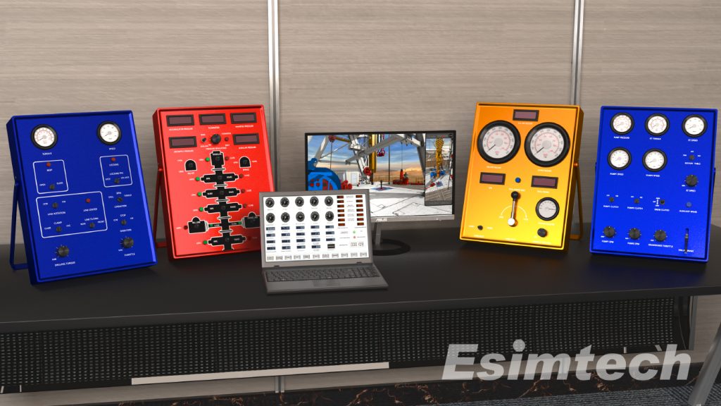
Key Aspects of Simulation Technology Used in a Drilling Course
Modern drilling courses increasingly incorporate simulation technology, providing participants with a realistic and immersive learning experience that bridges the gap between theory and practical application. Simulation technology is crucial for training future professionals in the oil and gas industry by replicating complex drilling scenarios in a controlled environment.
1. Virtual Drilling Environments
Software-Based Simulations: Drilling courses often utilize sophisticated software to simulate the entire drilling process in a virtual setting. Participants can practice decision-making, problem-solving, and operational procedures without the inherent risks of real-world drilling operations.
Realistic Wellbore Models: Simulation technology creates wellbore models with realistic geological formations, downhole conditions, and other variables. This allows participants to interact with and respond to challenges they might encounter during actual drilling.
2. Drilling Rig Simulators
Hardware Integration: Some courses incorporate physical drilling rig simulators that mimic the look, feel, and functionality of real drilling equipment. These simulators include control panels, joysticks, and other interfaces that participants use to operate the virtual drilling rig.
Real-Time Feedback: Participants receive real-time feedback on their actions, allowing them to understand the immediate consequences of their decisions. This feedback loop is crucial for developing hands-on skills and reinforcing best practices.

3. Emergency Response Training
Scenario-Based Simulations: Simulation technology creates emergency scenarios, such as blowouts or equipment failures, where participants must apply their knowledge and skills to manage and mitigate the situation. This type of training enhances participants’ ability to respond effectively to unexpected challenges in high-stakes environments.
Evacuation Drills: Virtual emergency simulations can also be used to conduct evacuation drills, helping participants practice emergency evacuation procedures in a safe and controlled setting.
4. Team Collaboration
Multi-User Simulations: Some drilling courses leverage simulation technology to facilitate collaborative learning experiences. Participants engage in multi-user simulations, working together to solve problems and make decisions as a team, mirroring the collaborative nature of real drilling operations.
5. Data Analysis and Visualization
Post-Scenario Debriefing: After completing a simulation, participants review and analyze their performance through post-scenario debriefing sessions. This includes examining data, identifying areas for improvement, and understanding the consequences of their decisions on the drilling process.
Visualization Tools: Advanced data visualization tools help participants understand complex drilling data, trends, and patterns, enhancing their ability to interpret real-time data during actual drilling operations.
6. Adaptive Learning
Personalized Training Modules: Simulation technology allows for adaptive learning experiences, where participants focus on specific aspects of drilling operations that align with their learning needs. This personalized approach enhances the efficiency of the training process.
Conclusion
A drilling course is essential for anyone looking to launch a successful career in the oil and gas industry. These courses are critical for developing skilled and responsible professionals who can contribute to the industry's long-term growth.
Incorporating simulation technology into drilling courses not only enhances the educational experience but also helps develop highly skilled and well-prepared professionals. The hands-on, risk-free nature of simulations is a valuable complement to traditional classroom instruction, ensuring participants are well-equipped to handle the complexities of real-world drilling scenarios.