Offshore oil rig decommissioning is a complex, multi-step process that involves dismantling, removing, and managing the environmental impact of aging oil and gas platforms. As more offshore rigs reach the end of their production life, decommissioning has become a vital part of the oil and gas industry. Executing these projects effectively requires a well-coordinated approach to manage environmental, financial, and operational aspects. Here’s a guide on how to excel in offshore oil rig decommissioning, from planning to safe disposal.

1. Conduct Comprehensive Pre-Decommissioning Assessments
Before beginning the decommissioning process, it’s essential to carry out a thorough assessment of the rig and the surrounding environment. This involves:
Engineering Surveys: Detailed structural and engineering surveys identify the rig’s condition and any modifications made over its lifetime.
Environmental Impact Assessment (EIA): The EIA identifies sensitive habitats, marine life, and protected areas around the rig. This assessment helps design an environmentally responsible approach and reduce ecological impact.
Risk Assessment: Evaluate the risks associated with the decommissioning, including potential hazards to workers and the environment. Assessing risks enables the development of contingency plans and safety measures.
By conducting these assessments, you lay the groundwork for a smoother and safer decommissioning project.
2. Develop a Clear and Detailed Decommissioning Plan
A well-defined decommissioning plan is crucial to coordinate various stages, minimize risks, and control costs. This plan should include:
Project Timeline and Phases: Define clear stages such as plug and abandonment of wells, topside removal, and site clearance.
Budget and Financial Planning: Outline expected costs, including contingencies for unexpected expenses.
Compliance Strategy: Address regulatory requirements from relevant authorities, including permits, documentation, and compliance with national and international regulations.
A clear decommissioning plan keeps the project on track, meets legal obligations, and helps prevent delays and cost overruns.
3. Prioritize Safety in Plugging and Abandonment of Wells
The first technical step in decommissioning is plugging and abandoning (P&A) wells. This process requires specialized equipment and expertise to permanently seal the wells, minimizing future environmental risks. Key steps in well P&A include:
Clearing Residual Hydrocarbons: Ensure that the well is cleared of any residual oil or gas.
Installing Cement Plugs: Place cement plugs at strategic points to prevent fluid migration, as required by regulatory standards.
Pressure Testing: Conduct pressure testing to verify that the cement seals are secure and effective.
Since well P&A is complex and potentially hazardous, strict adherence to safety protocols and advanced training for personnel are critical to prevent accidents and leaks.
4. Choose the Right Decommissioning Method
Selecting an appropriate method for dismantling the rig is essential to minimize environmental impact and adhere to regulations. The primary methods include:
Full Removal: Involves complete dismantling and removal of the rig, including the jacket, topside, and substructures. Full removal is often the preferred method to restore the site to its original state.
Partial Removal: Some portions of the structure, particularly those below the seabed, are left in place, which can minimize costs and provide artificial reefs for marine life.
Rig-to-Reef Conversion: The structure is repurposed as an artificial reef to support marine ecosystems, which may be viable in some locations depending on environmental and regulatory considerations.
Careful evaluation of these options helps balance costs, ecological impact, and regulatory compliance, ensuring the best outcome for each specific project.
5. Implement an Environmentally Responsible Dismantling Process
Environmental stewardship is crucial in decommissioning. An environmentally responsible approach includes:
Waste Management: Develop a comprehensive plan for waste disposal, recycling, and repurposing materials, such as metals, plastics, and hazardous substances.
Marine Life Protection: Schedule decommissioning activities to avoid critical periods for local marine life, like breeding seasons, and consider the use of noise reduction technologies to protect marine mammals.
Pollution Prevention: Implement strict procedures to prevent accidental spills or leaks, including secondary containment for fuels and chemicals and regular monitoring of water quality.
Following best practices in environmental management minimizes ecological damage, aligning decommissioning activities with sustainable practices.
6. Use Advanced Technology for Dismantling and Site Clearance
Deploying advanced technology and equipment can increase the efficiency and safety of the decommissioning process. This includes:
Remote-Controlled Underwater Vehicles (ROVs): ROVs are invaluable for underwater inspections, cutting, and removing subsea structures. They reduce risks for divers and improve precision in dismantling.
Specialized Cutting Tools: Utilize diamond wire and abrasive waterjet cutters to dismantle metal structures efficiently while minimizing environmental impact.
Site Clearance and Survey Tools: Conduct post-decommissioning surveys to ensure that all debris and structures have been removed or are in compliance with site clearance standards.
Using advanced technologies reduces risks and ensures thorough site clearance, helping meet regulatory and safety standards.
7. Engage Stakeholders and Communicate Transparently
Successful decommissioning requires coordination with multiple stakeholders, including regulatory bodies, environmental organizations, and the public. Transparent communication fosters trust and ensures that all parties are informed of the project’s progress. Key strategies include:
Regular Reporting: Provide updates to stakeholders at key project milestones, including environmental impact mitigation efforts and compliance with regulations.
Stakeholder Consultation: Engage with local communities, environmental groups, and regulatory authorities early in the process to address concerns and gather input.
Public Transparency: Share decommissioning plans, environmental reports, and post-decommissioning monitoring data with the public to build trust and demonstrate commitment to environmental protection.
Effective communication with stakeholders reduces potential conflicts and supports smooth project execution.
8. Post-Decommissioning Monitoring and Site Restoration
Once the rig is dismantled, ongoing monitoring and restoration are essential to ensure the area is returned to a safe, stable state. Steps for post-decommissioning include:
Environmental Monitoring: Conduct regular environmental assessments to ensure no residual contamination or damage to marine ecosystems.
Seabed Restoration: If necessary, restore the seabed to encourage the recovery of marine habitats and prevent erosion.
Final Compliance Check: Complete all required documentation, and report compliance with decommissioning regulations and environmental standards to relevant authorities.
These measures confirm that the decommissioning process has met environmental and safety standards, contributing to sustainable offshore management.

How Simulation Technology is Used in Offshore Oil Rig Decommissioning
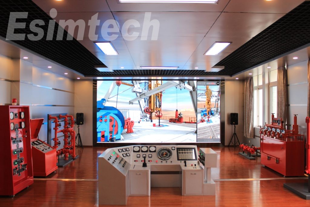
Simulation technology plays a vital role in offshore oil rig decommissioning, offering a virtual platform to model, test, and refine various aspects of the process. By simulating different stages, the oil and gas simulation tools enhance planning, safety, training, and operational efficiency in decommissioning projects. Here’s an overview of how simulation technology supports each stage of offshore oil rig decommissioning:
1. Rig Design and Planning
Virtual Prototyping: During initial planning, engineers create virtual models of the rig and its components. This enables them to test multiple decommissioning scenarios and optimize dismantling and removal strategies.
Structural Integrity Testing: Simulations assess the rig’s structural integrity, helping engineers understand load-bearing capacities and identify potential challenges before dismantling begins.
2. Buoyancy and Stability Analysis
Hydrodynamic Simulation: Modeling how the rig maintains buoyancy and stability under varying sea conditions is essential. Hydrodynamic simulations allow engineers to examine the interaction between the rig's structure, ballast systems, and ocean environment to ensure stability throughout decommissioning.
3. Drilling Processes
Drilling Simulations: For rigs with operational wells, simulations help optimize well plugging and abandonment. Simulating processes like plug insertion and cementing improves safety and ensures wells are securely sealed to prevent environmental hazards.
4. Dynamic Responses
Environmental Force Simulation: External forces, such as waves, wind, and currents, impact the rig’s stability. Simulations help predict the rig’s response to these dynamic elements, allowing engineers to plan accordingly to maintain stability during decommissioning.
5. Emergency Scenarios
Emergency Response Training: Simulation technology trains personnel for emergency situations, like blowouts or fires. Virtual scenarios allow crew members to practice evacuation procedures, well control, and other critical safety measures in a controlled environment.
6. Crew Training
Virtual Reality (VR) Simulations: Advanced VR simulations offer realistic training for rig personnel. Crew members can familiarize themselves with decommissioning operations, equipment, and safety procedures, gaining valuable hands-on experience before working on-site.
7. Equipment Testing
Machinery Performance Simulation: Decommissioning involves various machinery, including cranes and specialized dismantling equipment. Simulations test equipment performance, allowing engineers to optimize machinery configurations and identify potential issues proactively.
8. Data Integration
Real-Time Data Feeds: By integrating real-time data from operational rigs, simulation platforms allow operators to make informed decisions. This data-driven approach improves responsiveness to changing conditions and enhances situational awareness.
9. Optimization and Efficiency
Scenario Analysis: Simulation technology enables engineers to analyze different decommissioning scenarios, helping identify strategies to improve operational efficiency. Engineers can evaluate approaches to dismantling, waste disposal, and resource allocation.
10. Risk Mitigation
Risk Assessment Simulations: Simulations provide a safe platform to assess risks associated with decommissioning. By testing scenarios in a virtual environment, operators can identify potential hazards and develop strategies to enhance safety and minimize risks.
11. Research and Development
Testing New Technologies: Simulation accelerates the research and development of new technologies, equipment, and procedures. Virtual testing enables engineers to refine innovative solutions before they’re implemented on actual rigs, reducing the risk associated with new technology deployment.
Excelling in offshore oil rig decommissioning requires meticulous planning, cutting-edge technology, and a strong commitment to safety and environmental responsibility. By focusing on comprehensive pre-assessments, detailed planning, well abandonment, environmentally conscious dismantling, advanced technology, stakeholder engagement, and post-decommissioning monitoring, companies can ensure that offshore decommissioning projects are successful, safe, and sustainable. With the growing importance of decommissioning in the oil and gas industry, following these best practices is key to minimizing impact and maximizing operational excellence in offshore projects.
Advanced new materials, recognized for their unique properties—such as high strength-to-weight ratios, enhanced thermal stability, and exceptional flexibility—bring new challenges to manufacturing and processing. Among these challenges, tension control stands out as essential to ensure the quality, reliability, and performance of products derived from these materials.

Understanding Tension Control in Material Processing
Tension control is the regulation of the tensile force applied to materials during manufacturing processes like rolling, drawing, printing, and coating. Proper tension control is crucial for:
Preserving material integrity
Ensuring uniform thickness
Preventing defects, such as wrinkling, stretching, or breakage
Achieving the desired mechanical and physical properties in the final product
While tension control in traditional materials like steel or conventional polymers is relatively straightforward due to their predictable behavior under stress, advanced new materials—such as carbon-fiber composites, shape-memory alloys, and high-performance polymers—require novel approaches to handle their complex behaviors.
Challenges in Tension Control for Advanced New Materials
Material Heterogeneity and Anisotropy
Definition: Advanced materials, like carbon-fiber composites, are often heterogeneous (non-uniform) and anisotropic (properties vary by direction).
Challenge: Traditional systems are designed for isotropic materials, where properties are uniform in all directions. Anisotropy in advanced materials calls for customized tension control that accounts for varying strengths along different axes.
Sensitivity to Environmental Conditions
Definition: Many advanced materials are highly sensitive to factors like temperature, humidity, and chemical exposure.
Challenge: For instance, shape-memory alloys alter mechanical properties with temperature fluctuations. This sensitivity necessitates real-time tension adjustments, as environmental changes can significantly affect the material's behavior under stress.
Nonlinear Stress-Strain Behavior
Definition: Advanced materials often display nonlinear and time-dependent behaviors, such as viscoelasticity or plasticity, rather than the linear stress-strain behavior of traditional materials.
Challenge: This nonlinearity complicates tension control, requiring sophisticated models and systems to predict and manage the material’s response under varying stress conditions.
High Precision Requirements
Definition: Advanced materials are commonly used in applications that demand high precision, such as aerospace, medical devices, and electronics.
Challenge: Even slight deviations in tension can lead to defects like micro-cracks or delamination, which compromise product functionality and safety. Ensuring the necessary precision in tension control requires advanced systems capable of tight tolerances.
Complex Manufacturing Processes
Definition: Processing advanced materials often involves multi-stage techniques, such as layering, resin infusion, or high-temperature curing.
Challenge: Each manufacturing stage has unique tension control requirements. For example, during composite production, tension must be managed across fiber placement, resin application, and curing to prevent defects.
Dynamic Material Behavior
Definition: Some advanced materials exhibit dynamic behavior, where properties change during processing due to phase changes or chemical reactions.
Challenge: Managing tension for materials that undergo state changes requires real-time monitoring and adaptive control systems to respond to these transitions without causing damage.
These challenges underscore the need for advanced tension control systems tailored to the unique properties and processing requirements of new materials.

Solutions and Innovations in Tension Control for Advanced New Materials
Advanced Tension Control Systems
Solution: Leveraging real-time sensors, automated feedback loops, and machine learning, modern tension control systems precisely regulate tensile forces during processing.
Innovation: These systems dynamically adjust tension based on real-time data, adapting to changes in material properties, environmental conditions, and processing speeds for consistent quality.
Adaptive and Predictive Control
Solution: Adaptive control modifies operation in response to material behavior, while predictive control uses advanced modeling to anticipate changes.
Innovation: Predictive algorithms forecast material reactions to tension, enabling preemptive adjustments, especially beneficial for managing nonlinear, time-dependent behaviors seen in viscoelastic or shape-memory materials.
Integrated Process Control
Solution: Integrating tension control with other parameters, like temperature and speed, offers a holistic approach to material processing.
Innovation: In complex processes like composite manufacturing, synchronizing tension control with factors such as resin flow rates reduces risks of defects like delamination.
Material-Specific Control Strategies
Solution: Developing tailored strategies enhances processing outcomes for materials with unique characteristics.
Innovation: For anisotropic materials, control systems apply direction-specific tensions, preserving material properties. Custom algorithms can also account for stress-strain curves, providing precise control.

Real-Time Monitoring and Feedback
Solution: Real-time monitoring systems continuously measure material tension, offering immediate feedback for control adjustments.
Innovation: High-resolution sensors and data analytics allow instant corrections, maintaining the tight tolerances required for critical applications like aerospace or medical devices.
Smart Materials and Self-Regulating Systems
Solution: Developing smart materials that can self-regulate tension or provide stress feedback is an emerging area.
Innovation: Some materials incorporate embedded sensors or actuators to adjust tension automatically. For instance, composites with piezoelectric elements can modify tension in real-time, reducing dependency on external control systems.
Simulation and Digital Twins
Solution: Simulation tools and digital twins model and predict tension scenarios before production.
Innovation: Digital twins create virtual replicas of materials and processing environments, allowing risk-free testing and optimization of tension strategies for efficient, accurate production runs.
Overcoming the challenges of tension control in advanced materials relies on these innovative solutions. As industries adopt these materials, implementing advanced tension control systems will be essential for high-quality, efficient manufacturing.
Yushuo boat cabin lights have become an indispensable part of modern ship lighting. This article aims to comprehensively introduce the the classification, characteristics and maintenance methods of Yushuo boat cabin lights to enhance users’ understanding and application of this important lighting system and contribute to the shipping industry.

Specific Classification of Boat Cabin Lights
Boat cabin lights serve a dual purpose: providing illumination and enhancing the ambiance of the interior space. They can be classified based on their function, location, and light source.
Based on Function
General Lighting: Provides overall illumination for the cabin, allowing occupants to navigate and perform tasks comfortably.
Task Lighting: Designed to illuminate specific areas or activities, such as reading, cooking, or working.
Accent Lighting: Used to highlight architectural features, artwork, or decorative elements, creating a mood or atmosphere.
Based on Location
Overhead Lights: Mounted on the ceiling to provide general illumination.
Wall Lights: Installed on the walls, often used for accent lighting or task lighting.
Under-Cabinet Lighting: Located beneath cabinets or countertops for task lighting.
Portable Lights: Handheld or battery-powered lights that can be moved around the cabin as needed.
Based on Light Source
Incandescent Lights: Traditional bulbs that emit light through a heated filament. They are gradually being replaced by more energy-efficient options.
Fluorescent Lights: Tubes filled with a gas that emits light when an electric current passes through it. They are more energy-efficient than incandescent bulbs but are often larger and less versatile.
LED Lights: Light-emitting diodes that consume less energy and have a longer lifespan compared to incandescent and fluorescent bulbs. They are available in various colors and styles, making them a popular choice for boat cabin lighting.

Additional Considerations:
Dimming Capabilities: Many modern boat cabin lights offer dimming features to adjust the light intensity according to the desired ambiance.
Waterproofing: Since boat cabins are exposed to moisture, it's essential to choose lights that are specifically designed for marine environments and have appropriate waterproofing ratings.
Aesthetic Appeal: The style and design of boat cabin lights should complement the overall interior décor and create a welcoming atmosphere.
By carefully considering these factors, boat owners can select the most suitable lighting solutions for their cabin, ensuring both functionality and aesthetic appeal.
Features of Yushuo Boat Cabin Lights
Yushuo boat cabin lights is engineered with innovative technology to offer superior brightness, energy efficiency, and longevity.
1、Advanced LED Technology
Yushuo marine cabin lights integrate advanced LED technology, offering energy efficiency, long lifespan, and durability against shock and vibration. These lights provide a wide color temperature range, instant on/off, low heat generation, and environmental sustainability. They ensure high brightness with uniform distribution, customizable solutions, and smart lighting capabilities, making them ideal for marine environments.
2、Robust Construction
Made of marine-grade aluminum or stainless steel to resist corrosion, high-quality glass or polycarbonate lenses to protect against impact, and sealed to a high IP rating to prevent water and dust intrusion, they also feature anti-vibration mounting, UV-resistant coatings, and temperature-regulated designs to ensure reliable operation in harsh marine conditions.
3、Extensive Product Range
The marine cabin lights solutions from Yushuo encompass a broad spectrum of lighting options, from navigation signal lights and spotlights to explosion-proof and naval lighting, along with customizable LED services. This comprehensive range is designed to accommodate the unique lighting demands of different marine settings, providing marine operators and manufacturers with flexible choices and reliable lighting assurance.
4、Safety and Compliance
All products are professionally certified to meet or exceed international safety standards, including CE, CCS, ABS, DNV, and more, ensuring safety and compliance with global maritime regulations.
5、Exquisitely Elegantly Designed
Exquisitely elegantly designed, these boat cabin lights offer a sophisticated silhouette that enhances marine interiors with a touch of style, blending seamlessly into the nautical aesthetic while providing superior illumination.
6、Durable and Long-lasting
The marine cabin lights from Yushuo are celebrated for their exceptional longevity, with a service life that can extend beyond 50,000 hours. This impressive figure is a testament to their robust construction and the use of high-quality LEDs, which are not only energy-efficient but also resistant to the corrosive and vibrating conditions common on the high seas. As a result, these lights minimize maintenance requirements and offer a reliable source of illumination for maritime applications, ensuring a cost-effective and enduring solution for years to come.
7、Environmental Friendly
Offering a green approach to maritime lighting, the LED lights are crafted for sustainability. They’re mercury-free, recyclable, and designed to use minimal power, thereby reducing energy consumption and carbon emissions. With a long lifespan, these lights cut down on replacement needs, lessening waste and safeguarding the marine environment for the future. This commitment to sustainable lighting ensures a brighter, healthier ocean.

Maintenance and Care of Boat Cabin Lights
1、Installation and Use of Lighting Fixtures
Ensure that the bulb’s specifications, voltage ratings, and power consumption align with the lighting fixture’s capacity. The voltage of the bulb should match the supply voltage to prevent damage.
Avoid changing bulbs when the power is live. If this is unavoidable, take precautions not to look directly at the bulb to prevent injury from potential shattering and ensure the base is secure to avoid short circuits.
Onboard, refrain from using high-pressure portable lights except for cargo hold lights. In oily areas like engine rooms, use low-pressure lights below 36V with safety guards. After using outdoor projection lights, check that the socket’s waterproof cap is tightly screwed on.
2、Maintenance Cycles and Technical Requirements for Lighting Equipment
Regular Lighting Equipment: Adhere to the principle of “who manages, who is responsible.” Responsible departments must ensure the equipment’s safety and conduct routine inspections, maintenance, and necessary performance and insulation tests as per company regulations.
Emergency Lighting Equipment: Conduct at least monthly efficacy tests to inspect the operation of the emergency lighting contactors. Address any malfunctions promptly.
Boat cabin lights can ensure the safety of navigation and the safety of people on board. Its classification and characteristics help us understand and use them. The knowledge of its installation and maintenance can be applied to life at any time, helping us to make better use of the same series of lighting devices at home. The knowledge of marine lighting equipment has great practical significance in our lives.
A panhead screw is highly valued in the fastener industry for its versatility and user-friendly design. Whether you’re a DIY hobbyist, a handyman, or a construction professional, understanding the unique qualities and uses of a panhead screw can help you choose the right fastener for your needs. This article will delve into what makes a panhead screw distinct, highlighting its design, key benefits, and popular applications.

Basic Overview of a Panhead Screw
A panhead screw features a slightly convex, rounded head that resembles a shallow pan, giving it its distinctive name. It typically comes in Phillips (often referred to as a "pan head Phillips screw") or slotted drive options, with other varieties like Torx or square drive types also available, known as "pan head torx screws"

Features and Advantages of a Panhead Screw
Head Design
The rounded, slightly convex head of a panhead screw provides a broader surface area, enabling even force distribution and preventing it from sinking too deeply into the material. This design supports flush or slightly raised installation depending on countersink depth, making it suitable for various projects.
Versatility Across Applications
Known for adaptability, panhead screws are commonly used in woodworking, furniture assembly, electrical installations, and metalworking. They provide secure fastening in any application requiring a reliable, durable solution.
Easy Installation
Designed for convenience, the panhead screw’s broader head allows easy installation with a standard screwdriver or power drill. The larger surface provides a better grip, reducing slippage during installation, which is beneficial for DIY projects and professional work.
Secure Fastening
Panhead screws offer high holding power due to their wide head, which enhances surface contact and ensures even force distribution. This feature reduces the risk of pull-out or material damage, creating a more reliable connection.
Resistance to Stripping
Screws with Phillips or Torx drivers, common in panhead designs, are less likely to strip compared to slotted types. Panhead philip machine screws driving in allows better torque transfer and minimize the chance of the screwdriver slipping.

Aesthetic Appeal
With their rounded, low-profile heads, panhead screws often provide a clean, visually pleasing finish. When installed properly, they blend smoothly with surrounding materials, enhancing the project's appearance.
Variety in Size and Material
Panhead screws are available in various sizes and materials, including stainless steel, brass, and zinc-plated steel, allowing selection based on specific project requirements such as corrosion resistance, strength, and aesthetics.
Countersink Compatibility
Panhead screws work well with countersinking, a technique used to create a recess for the screw head to sit flush or slightly below the material’s surface. This helps achieve a polished appearance and prevents the head from protruding.
Common Applications of a Panhead Screw
Woodworking
Widely used in cabinetry, furniture assembly, and general joinery, panhead screws offer strong attachments and minimize the risk of wood splitting.
Electrical Fixtures
Ideal for mounting electrical plates, outlets, and light fixtures, panhead screws provide stability and prevent plates from loosening over time.
Metal Fabrication
Used for securing metal sheets or components, panhead screws distribute load evenly, reducing the likelihood of deforming or damaging metal surfaces.
General Construction
Common in various construction tasks like drywall installation, door hinge fixing, and hardware attachment, panhead screws are dependable and robust fasteners for building projects.
In summary, panhead screws are versatile, durable fasteners suited for a wide range of applications. Their rounded, broad heads offer secure attachments while distributing force evenly across surfaces, making them a reliable choice for woodworking, electrical setups, and construction tasks. By understanding their features and applications, you can select the ideal panhead screw for any project, ensuring professional, lasting results.
X-ray diffraction (XRD) is an essential analytical technique for characterizing material structure and composition. However, the precision and reliability of XRD measurements rely significantly on meticulous sample preparation. This article discusses best practices for preparing various sample forms for XRD analysis to ensure optimal results.

General Guidelines for XRD Sample Preparation
Before addressing specific sample types, it’s essential to consider some general principles for XRD sample preparation:
Homogeneity: Achieving sample uniformity is crucial for accurate XRD data. Non-homogeneous samples can lead to inaccurate diffraction patterns, potentially resulting in incorrect conclusions. Using proper grinding, mixing, and blending methods can help ensure uniformity throughout the sample.
Minimizing Surface Effects: Surface properties, like roughness and preferred orientation, can impact XRD results by distorting peak positions and intensities. Surface polishing can mitigate these effects, leading to clearer, more accurate data.
Avoiding Contamination: External contamination introduces unwanted peaks and affects sample analysis. Handling samples in a clean, controlled environment and regularly cleaning equipment can reduce contamination risks.
Sample Handling Techniques: Maintaining sample integrity is essential during preparation. Gentle handling methods, such as mild grinding and careful mounting, prevent mechanical stress or damage, preserving sample quality.
By following these general guidelines, researchers can enhance XRD sample quality, ultimately improving measurement reliability.

Best Practices for XRD Sample Preparation Across Different Forms
X-Ray Diffractometer analysis is commonly applied to crystalline and semi-crystalline materials in several forms. Here are best practices for the primary types:
Powder XRD Sample Preparation
For powder samples, the following steps help ensure accurate XRD data:
Grinding and Crushing: Fine grinding into a homogenous powder is crucial for XRD analysis. Mortar and pestle or ball mills can achieve fine particle sizes, typically in the micrometer range.
Homogenization: After grinding, further homogenization may be needed. Techniques like mixing or sieving can ensure uniform particle distribution, minimizing heterogeneity effects.
Mounting: Properly mounting the powder sample onto a holder using suitable adhesives ensures even coverage and stability during measurement.
Surface Smoothing: Flattening the powder surface through light tapping or compressing can reduce irregularities, improving data quality. Excessive compaction, however, should be avoided to prevent orientation biases.
Backfilling: Filling voids in the sample holder with a low-absorbing material like silicon powder helps reduce orientation effects, enhancing scattering uniformity.
By following these best practices, powder XRD samples can yield reliable, reproducible data essential for material characterization.
Solid XRD Sample Preparation
Solid samples, such as bulk or crystalline materials, require unique preparation steps:
Sectioning: Cutting solid samples with precision tools, like diamond saws or lasers, produces smooth, defect-free surfaces for XRD.
Surface Polishing: Polishing surfaces with finer abrasives, like diamond paste, removes cutting artifacts that could affect XRD results.
Mounting: Securely mounting polished samples prevents stress and maintains surface quality, ensuring accurate XRD readings.
Surface Protection: Applying a protective coating, such as wax or a polymer film, prevents sample degradation or contamination, preserving surface quality.
Calibration and Validation: Regular calibration using certified materials ensures measurement precision, making it essential before each XRD analysis.
Adhering to these practices allows precise, accurate characterization of solid samples, reflecting their true crystal structure and properties.
Thin Film XRD Sample Preparation
Thin films require specialized preparation for accurate XRD analysis:
Substrate Cleaning: Thorough substrate cleaning using solvents (e.g., acetone) removes residues that could impact deposition or XRD.
Deposition: Selecting an appropriate thin film deposition method, such as PVD or CVD, and optimizing parameters ensure desired film quality and uniformity.
Thickness Measurement: Techniques like ellipsometry or profilometry measure thin film thickness accurately, which is crucial for interpreting XRD results.
Mounting and Handling: Careful handling and mounting, such as with vacuum chucks, prevent film damage and contamination.
Specialized Environments: Low-background holders or specific environment chambers can enhance thin film data, particularly for in situ analyses under varying conditions.
Following these guidelines enables precise thin film XRD characterization, providing insights into film structure and composition.

Troubleshooting Common XRD Sample Preparation Issues
Sample preparation errors can degrade XRD data quality. Here are common issues and solutions:
Sample Orientation: Unintentional preferred orientation can distort data. Using random powder mounts or spinner stages helps ensure crystal randomness.
Sample Thickness: Overly thick samples absorb excessive X-rays, reducing intensity. Using thin samples (under 1 mm) minimizes absorption effects.
Particle Size: Large particles cause diffraction peak broadening. Fine grinding to particle sizes below 10 microns improves data quality.
Preparation Method: Inappropriate methods introduce contaminants. Selecting preparation techniques suited to the material reduces contamination.
Sample Mounting: Uneven mounting leads to poor illumination. Ensuring a flat surface and secure sample mounting optimizes data reliability.
Background Fluorescence: Samples with fluorescent elements affect diffraction patterns. Using monochromators or specific detectors reduces interference.
Sample Contamination: Contaminants introduce additional peaks, complicating analysis. Clean handling and equipment reduce contamination risks.
By addressing these challenges, researchers can consistently prepare high-quality XRD samples and achieve dependable results.
Effective sample preparation is the foundation of accurate XRD data across different sample forms. Adhering to best practices tailored to specific sample types and addressing common preparation challenges ensures high-quality XRD analysis. With meticulous preparation, researchers can achieve meaningful insights into material structure and properties through XRD analysis.