In the coil processing, due to the deviation of the coil itself or the machine, once the edge of the coil is not aligned, it will cause errors in subsequent processes, resulting in material waste or machine adjustment. In order to reduce the occurrence of such situations, the web guiding system can provide a solution for the edge position control of the coil.
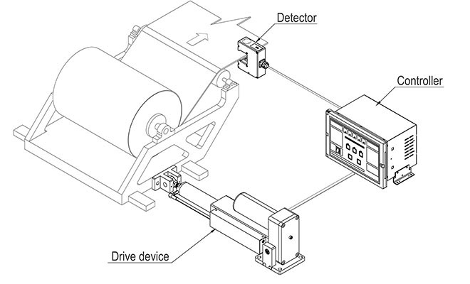
Web control refers to the technical operation that the coils must always be kept neat and consistent during the spraying, printing, punching, laminating, slitting, or other coil winding processes. When processing coils, it is necessary to perform edge guiding timely on the offset coils. This process is called web guiding. The equipment of the whole process constitutes a system. The web guiding system includes a controller, a web guide sensor, an electric drive, and a web guide mechanism.
The web guiding system is a closed-loop controller, which includes the controller, sensor, and web guide mechanism, as the basic complements of the system. First, the sensor detects the edge or of the coil, and the system automatically reads the offset of the actual position and the setting of the coil. Convert the offset into an electrical signal and send it to the controller. After the signal is amplified and calibrated by the controller, it is output to the driver. The linear driver drives the deviation correction mechanism according to the magnitude of the signal, to restore the coil to the set position. The drive signal of the current driver is only proportional to the deviation of the coil, which makes the web guiding system possible to provide precise control for various coils.
When the rolling speed of the material is relatively low, the speed of the motor should be low speed, otherwise, it will easily lead to over-correction. When the rolling speed is relatively high, then the speed of the motor should also be a high-speed correction. Adjust the winding speed of the correction motor through the frequency adjustment. The automatic web guiding can also be operated manually. It has the functions of automatic detection, automatic tracking, automatic correction, etc, which can track and correct the edges of paper, non-woven fabrics, film, aluminum foil, strip steel and other materials to ensure the roll winding and slitting neatly.
The web guiding system has a compact structure, good mechanical rigidity, low inertia, suitable for high-speed and high-precision edge position guiding in the middle of coil processing.
Web guide system can be widely used in various production processes of steel, corrugated paper, non-woven fabric, textile, printing, labeling, plastic film, building materials, etc. It can ensure continuous, precise control of the edges of the coil materials. Now we introduce useful tips about how to test the web guide system and daily maintenance.
How to test the web guide system
After the web guide system has been installed on the machine:
1. let the machine run first, if there is a deviation, adjust the upper layer of fabric firstly. For example, if it is to the left, it needs to be adjusted to the right. In the same way, if it turns to the right, you must adjust to the left.
2. Before turning on the web guiding machine, make sure that the fabric is aligned.
3. Then turn on the web guide equipment. After identifying the fabric, the probe is aligned with the red dot and the upper line is aligned with the edge. Then tighten the lower screw and the position will be located.
4.After locating the position, press the button of “automatic” mode. If there is an offset, it will all be aligned with the upper line.
5. Each layer is the same, and this layer should also be aligned with the red dot. The lower screw must be loosened firstly, and then the probe can be moved and aligned with the red dot.
6. After aligning the red dot and twist the black screw.
7. Then touch the “automatic” mode. If there is a deviation, the machine will swing and automatically correct it.
8. All the systems keep the "automatic" mode. Now the web guide runs automatically, and the machine will not run off when it starts.
Daily maintenance of the web guide system
Before the web guide system work
1. Check carefully whether the power switch and the indicator light of the web control system are normal.
2. Check whether the electric indicator light is normal and the sensitivity of the electric eye and the motor.
3. Whether the magnetic powder brake can be braked in time.
4. Fill the gear contact position with lubricating oil to maintain the lubrication between the wheels and reduce mechanical wear to ensure the precision of the web guide.
During the work of the web guide system
1. Is there any abnormality in the coordination of the electric eye, the control system, and the motor?
2.Listen to the sound, whether there is noise or excessive noise in the mechanical part.
3.Whether the temperature of the motor is too high.
After the work of the web guide machine
1. Turn off all power sources to prevent the rectifier from being on standby at any time.
2. Close the protective cover of the web guide control device to avoid objects hitting the device or damaging the control panel.
3. Protect the electric eye from damage by external objects.
4. Lubricate the motor bearings and screw rods.
5. Add lubricant to gears and magnetic powder brakes.
For more professional knowledge, please visit the page of web guide articles
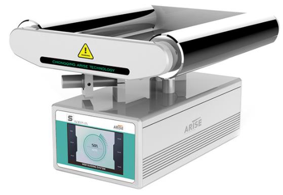
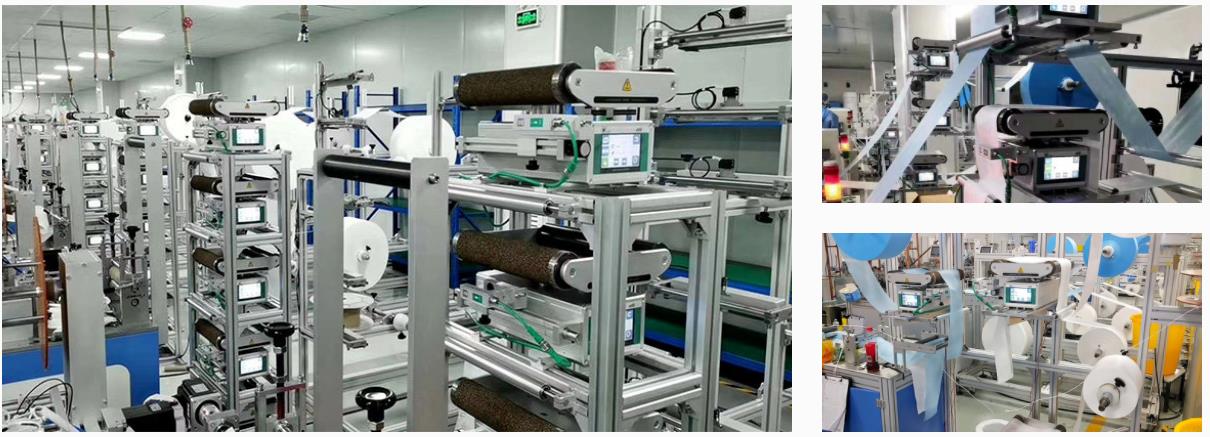
Arise all-in-one web guiding system can achieve multi-layer material alignment and there is no waste in the refueling process. The web guide system is an edge position controller for tracking the edge of the coil materials or printing lines for high-accuracy differential and swing. It is composed of large-scale industrial integrated circuits and has the advantages of high reliability and long service life.

Here are a few tips to operate the web guiding system after installation
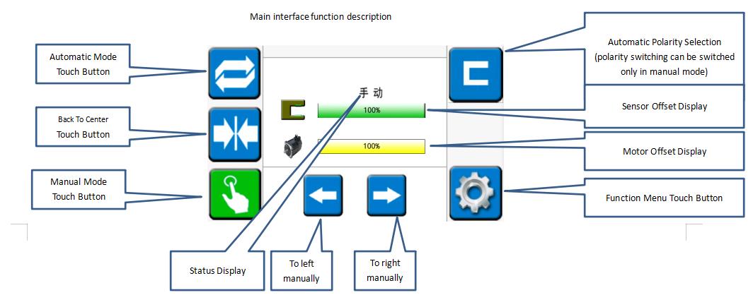
Operation of the main interface
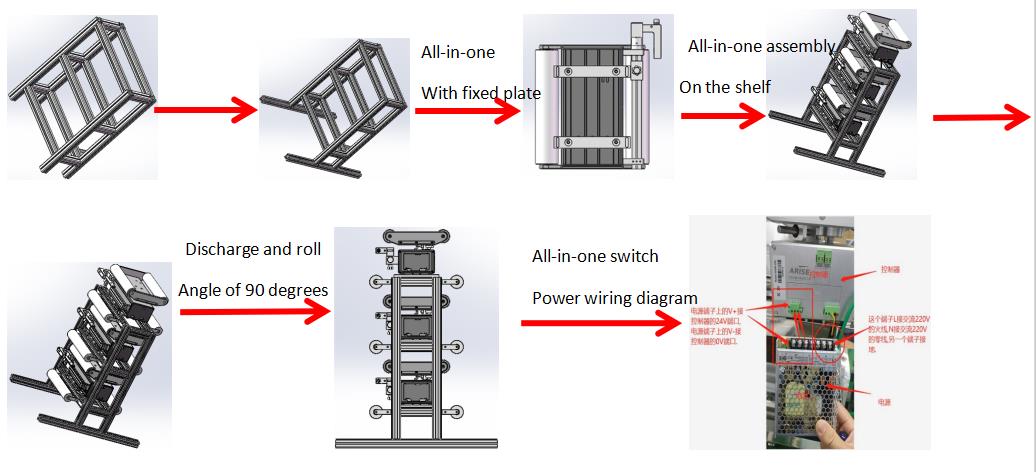
1. Install the rack and the all-in-one machine, plug the power and sensor plugs of the all-in-one into the corresponding sockets, and power on.
2. Enters the "manual" mode of the main interface and touch the "function menu" button. Then touch the "self-learning" button to enter the all-in-one self-adaptation and automatically return to "manual" mode.
3. Touch the "back to center" button, and then touch the "manual" button, respectively pressing the material of the same layer into the material according to the "material penetration diagram". Run the main machine for a few minutes to move the material for a period of time.
4. In the "manual" mode, adjust the sensor's position and the moving bracket in a large range and then adjust the rotary knob in a small range. (Adjust the position to the sensor offset display about 50%)
5. In the "automatic" mode, adjust the edges of the other layers of materials to coincide with the edges of the reference based on one layer, and the correction and debugging are completed.
Infrared sensor calibration
For some materials that are not easy to identify, the infrared sensor is required to achieve the best web guide effect.
Steps
1. Long press the "SET" button to make the sensor light flash (release the button after flashing)
2. Tighten the material and put it into the position of the sensor near the light lens (the material will completely cover the circular light-transmitting sheet). Then wait for 3 seconds and remove all the materials from the sensor.
3.Press the "SET" button until the light does not flash, and then release the button. The process of the calibration has been completed.

Common problems in the operation of the web guide system
1. The machine will swing to the limit alarm when it is switched to the "automatic" mode. (Confirm whether the correction polarity is correct and whether the sensor has a signal)
2. The speeds of the left and right swing are inconsistent in the "automatic" mode. (Check if the infrared sensor changes range from 0-100%)
3. When there are different materials in the "automatic" mode and the integrated machine does not swing, the infrared sensor is needed to calibrate the material.
If you have any question about the operation, please contact Arise web guiding.
A variably baggy or cambered web will cause the web to track toward the variably tighter side. Variabilities in roller traction or drag can cause a steering of the web. Changes in tension will cause changes in how straight the web travels downstream. At zero tension, edge position control is essentially lost. However, there are other edge movement factors which include nip roller draw variations, aerodynamics and so on. Web guides are used to bring the edge or center of a web to a specific CD position. The guide location may be at an unwind to get the web started down through a machine in a consistent position, at an intermediate location, or at the winder to improve roll edge quality. The accuracy demands for the guide may vary from merely keeping the web on the rollers, to minimizing trim loss, to registering several print colors to within a couple of mils. Guides may be either active or passive.
What is an acceleration offset
One of the most troublesome of the edge position excursions is known variously as the acceleration or ramp offset. Here, the web moves sideways when machine speed is increased or decreased. Usually the rate of movement is most severe at the top and bottom of the speed change rather than on the speed ramp itself. Unfortunately, the term “acceleration offset” belies the true nature of the cause of the edge movement. Indeed, the web does not even know how fast it is moving.
In the case of absolute traction, the web will conform to the Normal Entry law on all rollers, including the one that is misaligned. Note how the web moves over as the result of this misalignment. In the case of pure flotation, however, the web is not steered by the ‘roller’ and, thus, passes straight through the machine. The case of sliding is intermediate in that there is a small offsetting of the web.
Thus, every roller or element that touches the web also steers the web. However, if the roller is stationary and the state of traction constant, the path of the web will remain constant. That is not to imply straight. Obviously the web will snake through the machine in conformance to web handling laws.
However, if the web changes from full to partial tracking the path of the web will change slightly in response. This change in traction will be subtle and not easily picked up by conventional observations and measurements. Nonetheless, it will cause the web to move in response.
While there are many ways the state of traction can change, the most common is due to a tension change on a lightly wrapped roller. This means that if our drive allows tension variations, the web might shift slightly on some of the rollers. Furthermore, the condition which is most difficult to hold tensions is during a speed change.
Thus, as we not see, the acceleration offset is not due to the speed or speed change itself, but rather due to tension variations that can and will accompany the speed change. Our first efforts should then be to tune the drive so that tension is held well at sensors (load cells) as well as elsewhere where there are no sensors. Sometimes tension is held well only at the drive points or sensors, but not elsewhere because the web might be pulling against excessive roller inertia or drag.
However, we can also expect to reduce the severity of the offset if we reduce roller misalignment or other geometrical problems. The surest way to do this is through optical alignment of every roller in the line because even the lowly idler is as capable of shifting the web as any of the major process rollers. However, sometimes it is not the roller, but rather an air float oven, that is steering the web.
If you want to keep your web as uniform, flat, and baggy free as possible. This is because the web with profile troubles will merely exaggerate the difficulties discussed here. Only when material and machine are made true will edges run consistently.
How does the web guide system work?
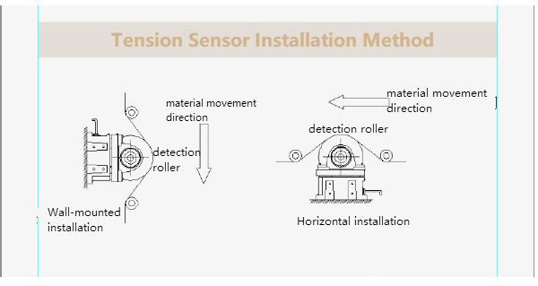
The active web guide system is composed of a sensor, an actuator, and a controller, which is a high-efficiency edge position control. The sensor can be any detector which can reliably pick up the edges of a web. The most common are pneumatic (nonporous webs), photoelectric (opaque webs), or paddies (thick webs). The web must be flat (free of curl) and stable (free of flutter) through the edge sensor. For this and other reasons, the sensor is often placed near a roller. If two sensors are used, the web could be guided to the front edge, back edge, or center.

The output of the sensor goes to a controller which outputs a movement command to the actuator. If the gain of the controller is too low, the response of the guide will be sluggish and slow to correct. If the gain of the controller is too high, the guide will be hot but overshoot, or may even be unstable. The actuator which moves the guide mechanism may be a stepper motor and ballscrew for smaller assemblies or a hydraulic cylinder for larger assembli`es. The actuator and framework must be stiff for responsive operation.
For more professional knowledge, please visit the page of web guide system articles.
Arise web guiding provides a high precision edge or marking line control with advanced technology and professional certificates, the most competitive price guaranteed.
How to install the web guide system
Mounting
1. Make sure to install the guide correctly according to the direction of the roll paper and the marks on the roller platform. The sensor must always be downstream on one side of the material flow.
2. Fix the guide on the machine by using the supplied bolts.
3. Tighten each bolt with a wrench by hand until each bolt is firmly locked. Do not tighten the bolts.
Installing the sensor
1.The sensor assembly consists of a sensor head, a sensor connection cable and two sensor carriages with M3 thumbscrews. All these elements are shipped from the factory.
2.Assemble into a ready-to-install unit.
3.Each sensor carriage will have a locking thumbscrew. Loosen the two thumbscrews to allow the carriage to slide into the sensor guide, which is installed under the roller assembly on the downstream side of the roll paper guide.
4.There is a filter cover (infrared or visible filter cover) on the surface of the sensor. When the sensor assembly slides into the guide rail, make sure that the filter cover faces the roll paper material.
5.After installing the sensor to the sensor rail, install the plastic end cap on the end of the rail. Clip-on plastic end caps are usually equipped with roll paper guides.
6. After installing the sensor, connect the sensor connector at the end of the sensor cable to the sensor port on the connector interface on the other side of the housing assembly.
Pre-wired
In the pre-wiring option, the equipment may be supplied with a 2.5-meter power cord (via compression nut) for customers to connect to a properly grounded 24 VDC power source.
Grounding
For safety and normal operation, a web guiding system is equipment used by the web and the installed guide plate must be properly grounded. The ground screw on the back connector is to connect the ground wire interface.
For more detailed information, please visit the aritcle page on how to install an all-in-one web guide system.