EPC is an abbreviation for edge position control. During the high-speed transmission process, the EPC web guiding system is used to manipulate and correct the direction deviation of the coil raw material. It performs real-time testing, active tracking, and active correction.

What Causes Acceleration Offsets In The Process Of The Edge Position Control
One of the most troublesome edge position deviations is known as the acceleration offset. When the machine speed is increased or decreased, the web moves sideways. The rate of movement is usually greatest at the top and bottom of the speed difference rather than on the speed ramp itself. Unfortunately, the term “acceleration offset” misrepresents the true nature of the edge movement. Indeed, the web has no idea how fast it is moving.
The various web tracks through a machine shown in Figure 6 illustrate the cause of most acceleration offsets. We demonstrate how the web moves through a machine with one of the rollers misaligned. When there is absolute traction, the web will follow the Normal Entry law on all rollers, including the misaligned one. Take note of how the web shifts as a result of this misalignment. However, in the case of pure flotation, the web is not steered by the ‘roller’ and thus passes directly through the machine. The case of sliding is intermediate in that there is a small offsetting of the web.
As a result, every roller or element that touches the web also steers it. The path of the web, on the other hand, will remain constant if the roller is stationary and the state of traction is constant. That is not to say it is straightforward. The web will obviously snake through the machine in accordance with web handling laws. What we mean is that the path will, for the most part, remain consistent.
However, if the web switches from full to partial tracking, the web’s path will shift slightly in response. This shift in traction will be subtle and difficult to detect using traditional observations and measurements. Nonetheless, it will move the web in response.
The EPC web guiding system provides edge alignment to avoid deviation of the waterproof coiled material during the entire production and processing process, as well as ensuring accurate and stable performance of the waterproof coiled material during the entire production process with the neatly divided rewinding machine.
The control board can choose the method of tracking the edge or line based on the various raw materials and choose the electric eye test to take into account the requirements of various raw materials.

How Does The EPC Web Guiding System Work
A sensor, an actuator, and a controller comprise a web guiding system. Any detector that can reliably detect the edges of a web can be used as the sensor. Pneumatic (nonporous webs), photoelectric (opaque webs), and paddies are the most common (thick webs). Through the edge sensor, the web must be flat (no curl) and stable (no flutter). The sensor is frequently placed near a roller for this and other reasons. The web could be guided to the front edge, back edge, or center if two sensors are used.
The sensor’s output is routed to a controller, which sends a movement command to the actuator. If the controller’s gain is too low, the guide’s response will be sluggish and slow to correct. If the controller’s gain is too high, the guide will be hot but overshoot, and may even be unstable. For smaller assemblies, the actuator may be a stepper motor and ball-screw, while for larger assemblies, it may be a hydraulic cylinder. For responsive operation, the actuator and framework must be stiff.
Professional EPC Web Guiding System Provider- Arise
Arise is a leading EPC web guide system manufacturer in China. High-accurate Arise web guiding can ensure continuous, precise control of various coil materials in various manufacturing processes, ensuring that the material does not deviate from the correct position and minimizing waste and downtime.
The land rig installation simulation training system is a simulation training system with advanced technology and complete functions in the current industry. It can meet the training needs of oil companies and training institutions.
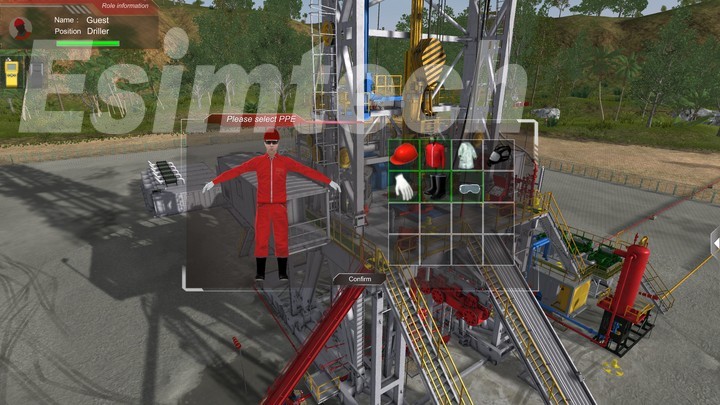
The simulation system is a training product developed based on computer simulation technology by combining petroleum engineering technology with computer technology and virtual reality technology. It simulates the drilling process of the land drilling rig realistically with reference to the actual operation process of the drilling operation site. The training objects are mainly technical skills training for new employees, drilling rig installers, drillers and assistant drillers, drilling team technicians, drilling team leaders, and other drilling site operators.
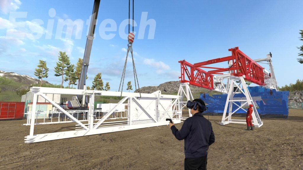
Compared with the traditional training method, it enhances the sense of participation and immersion in the training, effectively improves the training effect, and reduces the training cost. The system can train trainees, including the whole process of land drilling rig installation and safety precautions, the lifting and lowering process of land drilling rig derrick base, drilling rig tripping, and drilling operations, and top drive operations.
The Composition of the Land Drilling Rig Installation Simulation Training System
The Training System Mainly Consists of 5 Components:
The animation display module of the whole process of rig installation
Derrick/base lifting and lowering training module
Rig Virtual Assembly Module
Drilling rig simulation operation module
Electronic Atlas
The simulation system adopts high-definition animation to clearly show the whole land drilling rig installation process, and the displayed process is completely consistent with the actual land drilling rig installation process steps. The purpose is to standardize the entire installation process, making the land rig installation process more standard, regulated, and safe.
The simulation system utilizes a large number of mathematical and physical models to simulate and display various parameter changes in engineering operations, such as pressure, torque, drilling speed, and more, by accurately reflecting the relationship between these physical parameters to achieve the same performance as the actual drilling rig.
The land rig installation simulator adopts virtual reality technology and computer simulation technology to construct a realistic perception environment. The three-dimensional animation synchronized with the operating conditions is used to display the scene on a three-channel ring screen or three-channel LCD, combined with high-simulation on-site sound effects, giving people an immersive experience.
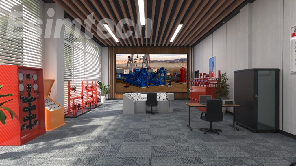
Components of a Training System for Land Rig Installation Simulator
Driller’s console
Top drive console
Graphic system
Supporting software
Advantages of a Land Rig Installation Simulation Training System
1. The parameter display, layout, and even operation mode of various equipment panels in the system are completely consistent with the actual products. And the height of each operation console and the real equipment on the drilling site is also the same.
2. The relevant hardware equipment is composed of industrial-grade PLC to ensure the reliability of the equipment to the greatest extent possible.
3. The system’s input cost and maintenance cost is relatively low.
4. The system has no security risk.
The technical operation for the coil materials that must always keep the edge of the coils neat and consistent during the spraying, printing, punching, laminating, slitting, or other coil winding processes is referred to as web guide control. The equipment used in the guiding process is a collection of web guiding control system. A common system consists of a controller, a sensor, a guide mechanism, and a driver.

Webs do not always track down through a machine in the same place. Any offsets in the unwinding roll, for example, will cause the web to start through a machine in a variable CD (cross direction) position on a roll-to-roll operation. Even if a web begins in the position, it may take slightly different paths through the machine depending on a variety of factors.
First, a variably baggy or cambered web will cause the web to track toward the variably tighter side. Second, variations in roller traction or drag can cause web steering. Third, changes in tension will affect how straight the web travels downstream. At zero tension, edge position control is essentially lost. Other edge movement factors include nip roller draw variations, aerodynamics, and so on.
Web guides are used to move the web’s edge or center to a specific CD position. The guide location could be at an unwind to start the web down through a machine in a consistent position, an intermediate location, or the winder to improve roll edge quality. The guide’s accuracy requirements can range from simply keeping the web on the rollers to minimizing trim loss and registering multiple print colors to within a few mils. Guides can be active or passive.
Working Of Web Guiding Control System
The purpose of the web guiding is to direct the sensor to emit infrared or ultrasonic radiation in order to monitor the operation of the coil material and send a signal to the controller. After the controller determines that the web has a positional deviation, the controller controls the drive system to swing to correct the web position using the preset command.
Brushless DC servo motor drive, precision ball screw drive, compact structure, good mechanical rigidity, low inertia, suitable for high-speed and high-precision guide are used in the web guiding system.
A controller, a sensor, an electric driver, and a correction guide mechanism comprise the system. The sensor detects the coil material’s edge position and reads the deviation between the actual and set positions, converting the deviation into a voltage signal proportional to it. The signal is then sent to the controller. After the signal is amplified and calibrated by the controller, the signal is output to the electric driver, and the electric driver drives the guide mechanism to perform correction actions according to the magnitude of the input signal to guide the coil material to the preset position.

Advanced Web Guiding Control System From Arise
Arise is a leading manufacturer in China, offering advanced web guiding control system. It is suitable for paper, non-woven fabric, plastic film, self-adhesive label tape, aluminum platinum, hot-rolled strip steel, and other applications. To ensure the neat division of the rewinding machine, the edge or marking line should be tracked and guided by the control border. The photoelectric correction manipulator uses a universal photoelectric controller for edge and line alignment, as well as imported drive machinery and a high-precision controller to control and maintain the edges or lines in a specific direction. The operation of the web guiding machine is simple, with high precision and reliability.
With the continuous development of 3D animation technology, 3D oil and gas animation also came into being, and oil animation is also a kind of three-dimensional animation.
Esimtech can provide oil drilling and well control animation, land rig installation animation, downhole tool disassembly and working principle animation, diesel engine disassembly, and assembly animation, and so on.
Why do We Need Drilling Animation?
The purpose of drilling animation is mainly to three-dimensional and visualize the equipment and technology in the oil industry and the complex mechanical design drawings. Various working processes, equipment technologies, etc., are made into 3D video demonstrations or interactive multimedia programs in the form of animation for engineering simulation or public display.
Types of Industrial Drilling Animation
Well Control Animation
It mainly shows different types of well control operations in the form of animation, including the installation and use of well control equipment. Let the students understand the real well control process more intuitively.
Well Logging Animation
It includes the appearance, logging principles, and uses of various logging tools such as compensated neutron logging, electrical survey, dual laterolog, spontaneous-potential log, and natural gamma-ray logging. And it contains the operation method of instrument connection.
Oil and Gas Production Animation
The animation of oil production and gas production includes the equipment working principle and production maintenance from the wellhead to the gas gathering station and the oil gathering station in the production process of oil and gas production.
Animation of Disassembly and Working Principle of Drilling and Well Control Equipment
The animation of drilling and well control equipment mainly trains the working principle, internal structure, and disassembly of drilling and well control equipment and tools in the form of animation. The purpose is to understand the components and principles of drilling and well control equipment and tools, to master the inspection and debug of the main working systems of drilling and well control equipment and tools, to analyze and judge the working conditions of drilling and well control equipment and tools, and can check and troubleshoot in time.
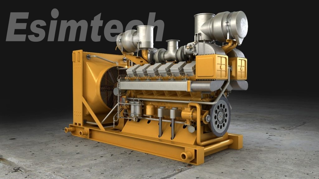
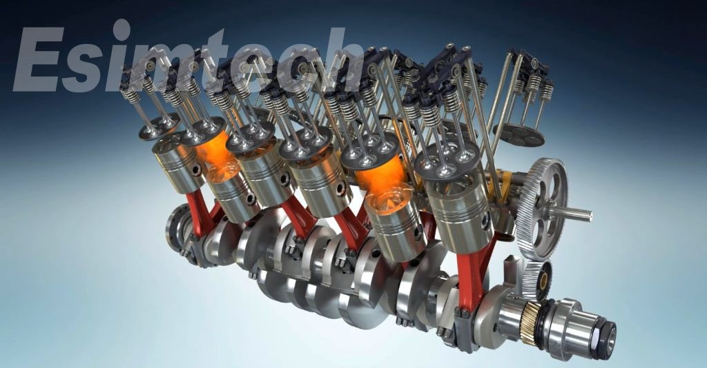
Diesel Engine Disassembly Animation
It mainly shows the internal structure and main components of the diesel engine. And it shows the disassembly, inspection, maintenance, and working principle of the diesel engine in the form of animation. At the same time, it is explained with text and dubbing so that the students are familiar with the working principle of the diesel engine and learn and master the inspection and debugging of the main working system.
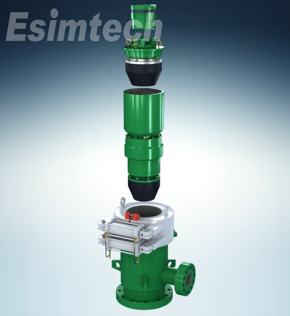
Downhole Tool Disassembly and Working Principle Animation
The animation shows the internal structure of the tool and the composition of the parts and shows the internal structure of the tool in the form of a half-section or semi-transparent shell. The disassembly and installation steps and working principles of the tools are shown in the animation. At the same time, the text and dubbing are used to explain so that the trainees can master the functions, working principles, precautions, and maintenance methods of various tools.
Land Rig Installation Animation
The animation includes the whole process, from the drawing of the baseline diagram to the installation of each object in the middle, and finally, the whole process of the whole derrick lifting is completed. All processes are completely reproduced according to the actual installation process. Watching the animation can quickly, clearly, and completely understand the whole process of the installation and lifting of the entire land drilling rig.
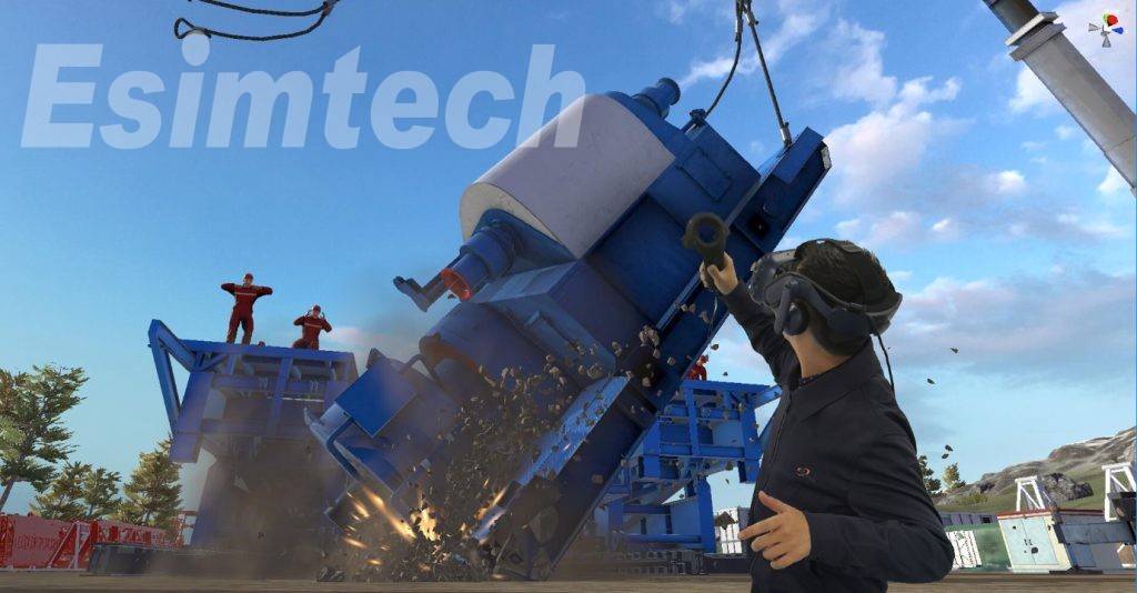
The virtual simulation platform for drilling emergency exercises in oil and gas fields uses three-dimensional simulation, three-dimensional interaction, network communication, and other technologies to construct and realize the simulation and 3D interaction of drilling scenes, equipment and facilities, personnel conditions, environmental conditions, accident occurrence, and development process and personnel emergency response process. The system can realize the emergency response simulation exercise of typical drilling accident disasters and complete single-person drills and multi-person joint drills for emergency response. And the simulator platform is able to conduct drill evaluations on trainees’ emergency handling operations, emergency handling, task completion, and related knowledge points and point out problems and deficiencies in the process of drills. Therefore, the platform can be used for drilling workers’ emergency response and rescue teaching training.
And after the drill, according to the students’ drill process, it can provide individual and team drill results, and then it can inquire about the reasons for the deduction of points.
The platform system can edit the drill program, support the selection of individual and team drill modes, set drill accident parameters, and generate drill process and evaluation criteria according to the parameter settings. It supports multi-point teaching, and the management of computers participating in the exercise can be realized through the teacher’s terminal.
About the student side of the emergency exercise simulation platform system
On the student side of the system, 3D simulation technology can realize emergency response and rescue training for drilling workers when they face dangerous accidents on site. Provides two exercise modes: individual exercise and team collaboration, which can be used to practice and assess the drilling process. The three-dimensional scene is realistic, the equipment is highly operable, and the environmental sound effects are added to make the simulation process close to reality. The training content is to realize emergency process simulation, risk identification, emergency response, rescue, and escape training according to the industry plan.
The system provides a rich knowledge base for trainers to learn and view relevant knowledge in practice mode and supports multi-person collaborative drills. And it provides training for personnel in various roles on the drilling site.
Advanced Technology in the emergency exercise simulation platform System
The system supports the execution of role AI and can automatically cooperate with trainees to complete the exercise project. It has a good user interaction experience. The equipment can be operated through an interactive interface, and the details are rich.
It has a multi-role information broadcast system, broadcasts the drill process in real-time, and judges whether the emergency response process is correct or not.
The simulation system uses CFD technology to realize model calculations such as gas diffusion and flame combustion and to deduce the accident process with real effects.