Whether producing intricate electronic components, sturdy construction materials, or delicate medical devices, maintaining uniform thickness is crucial for product performance and reliability. One crucial aspect of quality control is ensuring the thickness of materials meets specified standards. This is where in-line thickness measurement systems play a pivotal role.
Understanding In-line Thickness Measurement Systems
An in-line thickness measurement system is a sophisticated technology designed to measure the thickness of materials accurately and rapidly during the manufacturing process. Unlike traditional off-line methods, where samples are taken for measurement in a separate environment, in-line systems perform measurements directly within the production line, providing real-time feedback.

How Do In-line Thickness Measurement Systems Work
In-line thickness measurement systems are sophisticated instruments designed to measure the thickness of materials directly within the production line. These systems utilize various techniques and technologies to achieve precise measurements.
1. Integration into the Production Line
In-line thickness measurement systems are seamlessly integrated into the manufacturing process, typically positioned at strategic points along the production line where thickness measurements are required. They can be incorporated into existing equipment or installed as standalone units, depending on the specific application and requirements.
2. Sensor Technology
The heart of an in-line thickness measurement system lies in its sensors or probes. These sensors come in different forms, such as laser, ultrasound, x-ray, electromagnetic, or optical sensors, each tailored to suit specific materials and applications. The choice of sensor depends on factors like material properties, thickness range, and environmental conditions.
3. Measurement Principle
The sensors emit signals or waves towards the material being measured and capture the response to determine its thickness. The exact measurement principle varies depending on the type of sensor used:
Laser Sensors: Emit a laser beam onto the material surface and measure the time it takes for the beam to reflect back. By calculating the round-trip time and knowing the speed of light, the thickness of the material can be determined.
Ultrasound Sensors: Send high-frequency sound waves through the material and measure the time it takes for the waves to bounce back. The thickness is determined based on the speed of sound in the material.
X-ray Sensors: Emit x-ray radiation through the material and measure the attenuation or absorption of the radiation. Thicker materials absorb more radiation, resulting in lower intensity readings.
Electromagnetic Sensors: Generate an electromagnetic field around the material and measure changes in the field caused by variations in thickness. Thicker materials induce greater changes in the field strength.
Optical Sensors: Utilize light refraction or interference patterns to determine thickness variations in transparent or translucent materials.
4. Data Processing and Analysis
The measurements captured by the sensors are then processed and analyzed by dedicated software or algorithms. This software interprets the raw data, compensates for environmental factors (such as temperature or humidity), and calculates the precise thickness of the material. Advanced algorithms may also perform statistical analysis or pattern recognition to identify trends, deviations, or defects in the measured thickness.
5. Feedback and Control
Based on the analyzed data, the in-line thickness measurement system provides real-time feedback to operators or automated control systems. If the measured thickness deviates from the specified tolerances, corrective actions can be initiated to adjust manufacturing parameters, such as material flow rate, pressure, temperature, or machine settings, to bring the thickness back within acceptable limits.
Applications Across Industries of In-line Thickness Measurement Systems
In-line thickness measurement systems find diverse applications across a wide range of industries, where precise control of material thickness is critical for product quality, performance, and regulatory compliance.
1. Automotive Industry
Sheet Metal Production: In-line thickness measurement systems ensure uniform thickness in automotive body panels, chassis components, and structural parts, ensuring optimal strength, durability, and safety.
Coating Thickness Control: These systems monitor the thickness of paint, primer, and protective coatings applied to automotive surfaces, ensuring consistent coverage and adherence to quality standards.
2. Aerospace Industry
Composite Material Manufacturing: In-line measurement systems monitor the thickness of composite materials used in aircraft structures, such as fuselages, wings, and interior components, ensuring compliance with stringent aerospace standards and specifications.
Metal Alloys Production: For aircraft engine components and structural parts, in-line thickness measurement systems ensure precise control of metal alloy thickness during manufacturing processes like forging, machining, and heat treatment.
3. Electronics Industry
Semiconductor Wafer Production: In-line thickness measurement systems monitor the thickness of semiconductor wafers during fabrication processes such as polishing, etching, and deposition, ensuring uniformity and consistency for optimal electronic performance.
Printed Circuit Board (PCB) Manufacturing: These systems measure the thickness of copper layers, solder masks, and dielectric materials in PCB production, ensuring adherence to design specifications and reliable electrical performance.
4. Packaging Industry
Film and Foil Production: In-line measurement systems monitor the thickness of packaging films, foils, and laminates used in food packaging, pharmaceutical blister packs, and flexible pouches, ensuring barrier properties and product integrity.
Paperboard and Cardboard Manufacturing: These systems control the thickness of paperboard and cardboard substrates used in packaging boxes, cartons, and containers, ensuring dimensional stability and structural strength.
5. Construction Industry
Concrete and Asphalt Production: In-line thickness measurement systems monitor the thickness of concrete slabs, asphalt pavements, and road surfaces during production, ensuring uniformity, strength, and durability for infrastructure projects.
Insulation Material Manufacturing: These systems measure the thickness of thermal and acoustic insulation materials used in buildings and construction applications, ensuring energy efficiency and soundproofing performance.
6. Medical Device Industry
Catheter and Tubing Manufacturing: In-line thickness measurement systems monitor the thickness of medical-grade polymers and elastomers used in catheters, tubing, and implantable devices, ensuring precise dimensions and biocompatibility.
Packaging for Pharmaceuticals: These systems measure the thickness of packaging materials for pharmaceutical products, such as blister packs, vials, and pouches, ensuring compliance with regulatory requirements for product protection and stability.

Challenges and Future Solutions in In-line Thickness Measurement Systems
While in-line thickness measurement systems offer significant advantages, they also face several challenges that impact their effectiveness and reliability. Addressing these challenges requires continuous innovation and the development of solutions.
1. Calibration Drift
Over time, sensors used in in-line measurement systems may experience calibration drift, leading to inaccuracies in thickness measurements. This can result from factors such as sensor degradation, environmental changes, or wear and tear.
Future Solution: Implementing self-calibration mechanisms or using advanced sensor technologies with built-in calibration monitoring capabilities can help mitigate calibration drift. Additionally, regular maintenance and recalibration schedules can ensure the continued accuracy of measurement systems.
2. Material Variability
Different materials exhibit varying properties and behaviors, making it challenging to develop universal measurement techniques that apply across all materials. Factors such as material composition, surface finish, and opacity can affect measurement accuracy.
Future Solution: Advancements in sensor technology, including multi-sensor fusion and adaptive algorithms, can enable in-line measurement systems to adapt to different material properties and optimize measurement techniques accordingly. Machine learning and artificial intelligence algorithms can also be employed to enhance measurement accuracy by learning from historical data and adjusting measurement parameters in real-time.
3. High-Speed Production Environments
In-line measurement systems must operate effectively in high-speed production environments where materials move rapidly through the production line. Achieving accurate measurements within short timeframes presents technical challenges related to sensor response time and data processing speed.
Future Solution: Developments in sensor technology, such as high-speed laser scanners and ultra-fast signal processing algorithms, can enable in-line measurement systems to keep pace with high-speed production lines while maintaining measurement accuracy. Integration with advanced control systems and real-time data analytics platforms can further enhance system responsiveness and performance.
4. Complex Geometries and Surfaces
Some manufacturing processes involve materials with complex geometries or irregular surfaces, making it difficult to obtain accurate thickness measurements using traditional techniques. Surface curvature, texture, and reflectivity can pose challenges for measurement systems.
Future Solution: Advancements in sensor design, such as the development of flexible and adaptable sensor arrays, can enable in-line measurement systems to accommodate complex geometries and surface profiles. Incorporating advanced imaging techniques, such as structured light or depth sensing, can improve measurement accuracy on non-planar surfaces.
5. Integration with Industry 4.0 Technologies
In-line thickness measurement systems are increasingly being integrated into Industry 4.0 ecosystems, where they interact with other smart manufacturing technologies such as IoT devices, cloud computing, and cyber-physical systems. Ensuring seamless interoperability and data exchange between different systems poses integration challenges.
Future Solution: Standardization efforts and interoperability protocols, such as OPC UA (Open Platform Communications Unified Architecture), can facilitate seamless integration of in-line measurement systems with other Industry 4.0 technologies. Developing standardized interfaces and communication protocols will enable plug-and-play compatibility between different systems, fostering interoperability and data exchange.
Conclusion
In-line thickness measurement systems represent a critical advancement in quality control technology, enabling manufacturers to achieve higher levels of precision, efficiency, and consistency in their production processes. As industries continue to evolve, the widespread adoption of these systems is poised to catalyze further innovation, driving quality improvement and bolstering competitiveness across sectors.
The safety of crew and passengers aboard maritime vessels is paramount, and one of the critical components of maritime safety is the lifeboat launching system. These systems are designed to ensure that lifeboats can be quickly and safely deployed in the event of an emergency, providing a reliable means of escape and survival. This article delves into the various types of lifeboat launching systems, their components, and the regulations governing their use.
The Main Types of Lifeboat Launching Systems
1. Gravity Davits
Mechanism: Utilize gravity to lower the lifeboats.
Single Pivot Gravity Davit:
Description: The lifeboat is supported by davits with a single pivot point, allowing the boat to swing out and be lowered into the water.
Advantages: Simple design, reliable operation, and can be used without power.
Quadrantal Davit:
Description: Features a curved arm that moves the lifeboat outward and downward in a controlled arc.
Advantages: Smooth deployment path and compact design suitable for limited deck space.
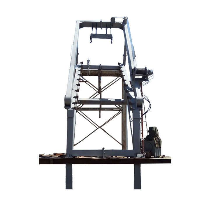
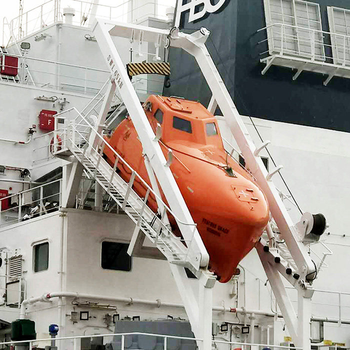
2. Free-Fall Lifeboat Systems
Mechanism: The lifeboat slides off an inclined ramp into the water.
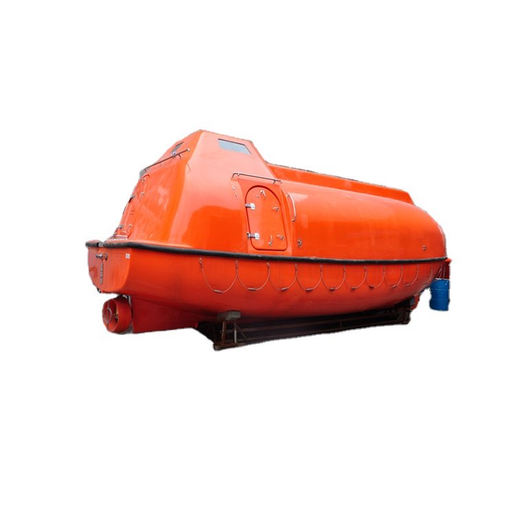
Description: Freefall lifeboats are launched from a considerable height, sliding down a ramp to enter the water quickly.
Advantages: Rapid deployment, reduces time spent on the ship during an emergency, and ensures the lifeboat is clear of the vessel.
3. Hydraulic Davits
Mechanism: Use hydraulic power to control the lowering and hoisting of lifeboats.
Description: Incorporate hydraulic cylinders and pumps to manage the movement of the lifeboats.
Advantages: Provides smooth and controlled operations, can handle heavier lifeboats, and allows precise positioning.
4. Mechanically Controlled Davits
Mechanism: Operated using mechanical gears and winches.
Description: These systems use manual or motor-driven winches and gears to lower and raise lifeboats.
Advantages: Reliable and can be operated manually if power is unavailable, providing an extra layer of safety.
5. Davit-Launched Lifeboats
Mechanism: The lifeboat is swung out over the side of the vessel before being lowered.
Description: Includes various types of davits (such as gravity and hydraulic) that can swing the lifeboat outboard before lowering it.
Advantages: Keeps the lifeboat clear of the vessel, minimizing the risk of damage during deployment.
Regulatory Standards Covering Lifeboat Launching Systems
1. International Maritime Organization (IMO)
SOLAS Convention: The International Convention for the Safety of Life at Sea (SOLAS) sets comprehensive standards for lifeboat launching systems, including design, testing, and maintenance requirements.
LSA Code: The Life-Saving Appliances (LSA) Code provides detailed specifications for lifeboat launching systems, ensuring they meet rigorous safety standards.
2. Classification Societies
Organizations such as Lloyd’s Register, Bureau Veritas, and the American Bureau of Shipping provide additional certification and inspection services to ensure compliance with international standards.
3. National Regulations
Individual countries may have their own regulations and standards that complement international guidelines, tailored to specific maritime operations within their jurisdiction.
Maintenance and Testing of Lifeboat Launching Systems
1. Importance of Maintenance and Testing
Regular maintenance and testing are not optional; they are lifesaving practices. By proactively identifying and addressing potential issues, these procedures ensure the lifeboat launching systems are in peak condition when needed most. A well-maintained and tested lifeboat launching system provides peace of mind for crews and passengers, knowing they have a reliable evacuation option in case of an emergency.
2. Maintenance
Regular Inspections: Lifeboat launching systems, including davits, winches, wires, hooks, and release mechanisms, undergo regular inspections according to a planned schedule. These inspections are typically weekly and monthly, as mandated by SOLAS.
Visual Checks: Inspectors look for signs of wear, corrosion, deformation, or any damage that could compromise the system’s operation. Lubrication of moving parts and ensuring proper alignment are also crucial maintenance tasks.
Record Keeping: Detailed records of all maintenance activities, including inspections, repairs, and replacements, are maintained onboard. This documentation helps ensure a complete service history and facilitates identification of any recurring issues.
3. Testing
Operational Tests: Lifeboat launching systems are not just inspected; they are also functionally tested regularly. These tests verify the davits’ ability to lower and raise the lifeboats at the required speeds under various loads, simulating real-world scenarios.
Release Gear Testing: The lifeboat release gear, which allows for quick detachment from the davit in an emergency, is rigorously tested. This ensures the simultaneous release of all hooks and proper functioning under load.
Free-Fall Lifeboat Testing: For certain types of lifeboats designed for rapid deployment, free-fall launch tests might be conducted periodically. These tests involve lowering the lifeboat with crew onboard a short distance to verify its functionality and crew readiness.
4. Frequency of Testing
The frequency of testing varies depending on the specific equipment and SOLAS regulations. Here’s a general guideline:
Weekly: Lifeboat winches and brakes are tested under light load.
Monthly: Lifeboats are lowered and raised under full load capacity.
Every 3 Months: Lifeboat release gear is functionally tested.
Every 6 Months: Free-fall lifeboat testing might be required (depending on the type).
Annual: A comprehensive operational test of the entire lifeboat launching system is conducted.
Conclusion
Understanding the various types of lifeboat launching systems and their components, along with the regulatory framework, ensures the maritime industry can maintain reliable and effective emergency response measures. Regular maintenance, testing, and training are essential practices that uphold the integrity of marine lifeboat launching systems, ultimately safeguarding lives at sea.
Bolted joints are crucial for ensuring the safety, reliability, and performance of equipment and structures. Among the essential techniques for bolt tightening are bolt torquing and tensioning, which ensure the proper clamping force necessary for maintaining the integrity of bolted connections.

Importance of Bolt Torquing and Tensioning
Safety
Properly torqued or tensioned bolts significantly reduce the risk of structural failure, equipment damage, and, most critically, injuries or fatalities resulting from bolted connection failure.
Reliability
Correctly tightened bolts maintain their clamping force over time, preventing loosening and enhancing equipment reliability, which in turn reduces maintenance and replacement costs.
Performance
Tightening bolts to the specified torque or tension ensures that the equipment or structure operates correctly, especially in high-stress applications subject to significant loads.
Cost Efficiency
Adhering to correct tightening practices extends the service life of bolts and reduces maintenance costs. Incorrectly tightened bolts can lead to premature wear, fatigue, or failure, resulting in costly repairs or replacements.
What are Bolt Torquing and Tensioning?
What is Bolt Torquing?
Definition:
Bolt torquing involves tightening a bolt to a specific torque setting using a torque wrench. Torque measures the rotational force required to turn a bolt to a precise degree of tightness. The required torque is determined by factors such as the bolt's size and grade, the material being secured, and the intended function of the bolted connection. It is crucial to use the correct torque setting to ensure proper security and avoid damage.
Advantages:
Precise Tightening: Ensures bolts are tightened to manufacturer specifications.
Consistent Results: Applies uniform force to each bolt, ensuring even tension distribution.
Reduced Risk of Damage: Minimizes over-tightening or under-tightening, protecting both the bolt and the material.
Disadvantages:
Difficulty with Certain Bolts: Hard-to-reach or high-tension bolts can be challenging to torque accurately.
Inaccuracy from External Factors: Variables like temperature, humidity, and lubrication can affect torque accuracy.
Specialized Equipment Required: Torque wrenches, which can be expensive and specific to bolt sizes and grades, are necessary.
What is Bolt Tensioning?
Definition:
Bolt tensioning involves applying a precise amount of tension to a bolt using hydraulic or pneumatic tools. This method is often used in applications requiring high-strength bolts to secure large loads or withstand extreme stresses. Tension is measured using a load cell, ensuring the bolt is properly tightened.
Advantages:
Accurate Results: Delivers precise and consistent tensioning.
Even Load Distribution: Ensures uniform load distribution, reducing localized stress.
High Strength: Suitable for heavy-duty applications requiring high tension.
Disadvantages:
Requires Specialized Equipment and Training: Necessitates hydraulic or pneumatic tools and proper training.
Risk of Over-Tightening: Potential damage from over-tensioning may be hard to detect initially.
Limited Accessibility: Challenging in areas with restricted access or obstructions.

Summary
In industrial applications, bolt torquing and tensioning are key methods for tightening bolts. Bolt torquing uses a torque wrench to apply a specific twisting force, while bolt tensioning applies a specific stretching force using hydraulic or mechanical tensioners. Torquing is simpler and cost-effective but may not suit all applications, whereas tensioning offers greater precision and is suitable for critical applications but requires specialized tools and expertise. The choice between these methods depends on the specific application requirements.
Marine signal products are vital tools that ensure safety and effective communication in maritime environments. These products help prevent collisions, facilitate navigation, and enable communication between vessels and shore facilities. In the vast and often hazardous marine environment, reliable signal products are indispensable for both commercial and recreational maritime activities. This article explores 4 key types of marine signal products, their uses, and their importance in maritime safety.

Marine Signal Lights
Marine signal lights serve as essential beacons, conveying vital information about a vessel’s position, status, and movements, especially in low-visibility conditions such as nighttime, fog, or heavy rain.
1. Navigation Lights
Navigation lights are mandatory on all vessels to indicate their presence, movement, and direction. These lights help prevent collisions by informing nearby vessels about a vessel’s type, size, and activity. The primary types of navigation lights include:

Sidelights (Port and Starboard Lights):
Port Light: A red light on the left (port) side of the vessel.
Starboard Light: A green light on the right (starboard) side of the vessel.
Purpose: Visible to vessels approaching from the side or head-on, indicating orientation and direction of travel.
Stern Light:
Description: A white light located at the rear (stern) of the vessel.
Purpose: Visible from behind the vessel, indicating its direction and providing a clear marker of its position.
Masthead Light:
Description: A white light placed on the fore-and-aft centerline of the vessel, typically above the deck.
Purpose: Visible from the front and sides, indicating the vessel’s presence and helping determine its direction of movement.
All-Round Light:
Description: A white light visible from all directions around the vessel.
Purpose: Used in various configurations, such as anchor lights or as a single light on smaller boats.
2. Anchor Lights
Description: A white light visible from all directions.
Purpose: Displayed by vessels when anchored, signaling that the vessel is stationary. This helps prevent collisions by alerting other vessels to its position.
3. Towing Lights
Description: A yellow light located above the stern light.
Purpose: Used on vessels engaged in towing operations to indicate that the vessel is towing another vessel. This information is crucial for nearby vessels to navigate safely around the towing vessel and its tow.
4. Specialty Lights
Certain vessels have additional lighting requirements based on their activities and regulations governing maritime operations. These specialty lights include:
Fishing Lights:
Description: Red over white or green over white lights.
Purpose: Used by fishing vessels to indicate they are engaged in fishing activities, helping other vessels avoid interfering with fishing operations.
Pilot Lights:
Description: White over red lights.
Purpose: Indicate that the vessel is a pilot boat, which guides other vessels into or out of ports, ensuring it receives the right of way.
Restricted Maneuverability Lights:
Description: Red, white, and red lights in a vertical line.
Purpose: Indicate that the vessel has restricted maneuverability due to its work (e.g., dredging or underwater operations). Other vessels should navigate with caution around it.
5. Emergency and Distress Lights
Emergency and distress lights are crucial for signaling when a vessel is in trouble and needs assistance. These include:
SOS Lights:
Description: Flashing lights that signal the international distress code (SOS).
Purpose: Used in emergencies to alert nearby vessels and rescue services to a vessel in distress.
Strobe Lights:
Description: High-intensity flashing lights.
Purpose: Used to attract attention during search and rescue operations.

Marine Flares and Pyrotechnics
Marine flares and pyrotechnics are primarily used for signaling distress and attracting attention during emergencies. These tools can be lifesaving in the vast and often perilous marine environment.
1. Types of Marine Flares
Marine flares are designed to be highly visible and are categorized based on their intended use and the type of signal they produce. The main types include:
Handheld Flares:
Description: Produce a bright, intense light, typically red.
Purpose: Used to signal distress, visible over long distances, both day and night.
Parachute Flares:
Purpose: Visible for miles, making them highly effective for attracting attention from ships or aircraft.
Smoke Flares:
Description: Emit dense, colored smoke, usually orange.
Purpose: Signal distress in daylight conditions and help mark a position for rescue operations.
Multi-Star Flares:
Description: Launch several bright stars into the air, spreading out and descending slowly.
Purpose: Provide a wider signal pattern, effective in both day and night conditions.
2. Pyrotechnic Signaling Devices
Beyond flares, other pyrotechnic devices are used for signaling in maritime environments:
Distress Rockets:
Description: Launch a flare to a high altitude, similar to parachute flares but may not always deploy a parachute.
Purpose: Send an immediate and highly visible distress signal.
Line-Throwing Devices:
Description: Use pyrotechnics to launch a line over long distances.
Purpose: Used in rescue operations to establish a line between vessels or to shore.
3. Regulations and Standards
The use of marine flares and pyrotechnics is regulated by international maritime organizations to ensure effectiveness and safety:
SOLAS (Safety of Life at Sea):
Description: Sets minimum standards for marine safety equipment, including flares and pyrotechnics.
Requirements: Vessels must carry a specific number and type of flares, depending on their size and voyage type.
US Coast Guard (USCG) Regulations:
Description: In the United States, the USCG sets standards for the types and quantities of distress signals that must be carried on boats.
Requirements: Recreational boats, commercial vessels, and certain passenger-carrying vessels must adhere to these regulations.
4. Usage and Safety
Proper use and handling of marine flares and pyrotechnics are crucial for their effectiveness and safety:
Storage: Flares should be stored in a dry, accessible location, protected from moisture and extreme temperatures. Expiry dates should be checked regularly, and expired flares should be replaced and disposed of according to local regulations.
Operation: Familiarize yourself with the operation of each type of flare. Practice using dummy versions if available, and follow the manufacturer’s instructions during an actual emergency.
Safety Precautions: Wear protective gloves and eye protection when handling pyrotechnics. Ensure flares are launched away from the body and any flammable materials. Be aware of wind direction to avoid exposure to smoke.
5. Significance in Maritime Safety
Marine flares and pyrotechnics are indispensable for several reasons:
Distress Signaling: Provide a clear and unmistakable signal that a vessel is in distress, facilitating quick response and rescue.
Visibility: The intense light and smoke produced by these devices are visible over long distances and in various conditions, ensuring that distress signals are seen.
Sound Marine Signaling Devices
Sound marine signaling devices allow vessels to convey their presence, movements, and intentions, particularly in conditions of poor visibility such as fog, heavy rain, or nighttime.
1. Types of Sound Signaling Devices
Several types of sound signaling devices are used on vessels, each serving specific purposes to aid in navigation and communication:
Whistles and Horns:
Description: Produce loud, distinct sounds that can be heard over long distances.
Purpose: Signal intentions, warnings, and responses to other vessels. Specific sound signals are outlined in the International Regulations for Preventing Collisions at Sea (COLREGs).
Bells:
Description: Traditionally used on larger vessels, produce a clear, ringing sound.
Purpose: Used in foggy conditions or during periods of restricted visibility to signal the vessel’s presence.
Gongs:
Description: Produce a deep, resonant sound.
Purpose: Used in conjunction with bells on larger vessels to provide additional audible signals.
Fog Horns:
Description: Produce low-frequency sounds that can travel long distances in foggy conditions.
Purpose: Signal the vessel’s position, course, and speed to nearby vessels.
2. Regulations and Standards
The use of sound signaling devices is governed by international regulations to ensure consistency and effectiveness in maritime communication:
International Regulations for Preventing Collisions at Sea (COLREGs):
Description: Set out the rules for sound signals to be used in various situations, such as maneuvering and warning signals.
Requirements: Vessels must be equipped with appropriate sound signaling devices and use them as specified.
SOLAS (Safety of Life at Sea):
Description: Includes provisions for sound signaling devices as part of the required safety equipment on vessels.
Requirements: Vessels must carry sound signaling devices appropriate for their size and type.
3. Usage and Significance
Proper use of sound signaling devices is crucial for maritime safety:
Maneuvering and Warning Signals:
Usage: Vessels use specific sound signals to indicate their maneuvers.
Significance: Help prevent collisions by clearly communicating a vessel’s intentions to nearby vessels.
Restricted Visibility Signals:
Usage: In foggy or low-visibility conditions, vessels use prolonged blasts at regular intervals to signal their presence.
Significance: Ensure vessels remain aware of each other’s presence and can navigate safely.
Emergency Signals:
Usage: Sound signals are used to indicate emergencies.
Significance: Quick and effective communication of emergencies can lead to faster response and rescue operations.
4. Modern Advances
Modern technology has introduced additional tools to enhance maritime communication:
Automatic Identification Systems (AIS):
Description: Transmits a vessel’s position, speed, and other data electronically.
Purpose: Enhances situational awareness and complements traditional sound signals.
Integrated Communication Systems:
Description: Combine traditional sound signals with visual and electronic signals.
Purpose: Improve the accuracy and reliability of maritime communication.
Electronic Marine Signal Devices
Electronic marine signal devices have revolutionized maritime navigation and safety, providing advanced tools for communication and situational awareness. These devices use modern technology to enhance traditional signaling methods.
1. Automatic Identification System (AIS)
Description: An automated tracking system using transponders on ships.
Purpose: Provides real-time information about a vessel’s position, speed, course, and other data.
Significance: Enhances situational awareness, collision avoidance, and navigational safety.
2. Radar and Radar Reflectors
Radar Systems:
Description: Use radio waves to detect objects and determine their distance, speed, and direction.
Purpose: Used for navigation and collision avoidance.
Significance: Helps detect other vessels, landmasses, and obstacles.
Radar Reflectors:
Description: Passive devices that reflect radar signals back to the source.
Purpose: Enhance the visibility of small or non-metallic vessels on radar screens.
3. Global Maritime Distress and Safety System (GMDSS)
Description: A set of safety procedures, equipment, and communication protocols.
Purpose: Ensures ships can send and receive distress signals and important maritime safety information globally.
Significance: Provides a comprehensive safety net for maritime operations.
4. Emergency Position Indicating Radio Beacons (EPIRBs)
Description: Emergency devices that transmit a distress signal via satellite.
Purpose: Used to alert search and rescue services in an emergency.
Significance: Ensure help can be dispatched quickly to the vessel’s exact location.
5. Automatic Radar Plotting Aids (ARPA)
Description: Advanced radar systems that automatically track targets and provide information on their course and speed.
Purpose: Aid in collision avoidance.
Significance: Enhance navigational safety.
6. Electronic Chart Display and Information System (ECDIS)
Description: A digital navigation system displaying electronic navigational charts.
Purpose: Provides real-time charting and navigational information.
Significance: Enhances situational awareness and route planning.
7. Vessel Traffic Services (VTS)
Description: Shore-based systems that monitor and manage vessel traffic.
Purpose: Provide information, navigational assistance, and traffic organization.
Significance: Enhance maritime safety by reducing the risk of collisions and groundings.
8. Digital Selective Calling (DSC)
Description: A digital communication technology used in maritime VHF radios.
Purpose: Allows automated distress signaling and direct calling to specific vessels or shore stations.
Significance: Improves the speed and reliability of distress communications.
Conclusion
From traditional lights and sound signals to modern electronic devices like AIS and EPIRBs, marine signal tools provide crucial information that aids in preventing collisions, guiding navigation, and signaling distress. Understanding and properly using marine signal products is essential for maritime safety, ensuring vessels can communicate effectively and navigate safely through various marine environments.
Directional drilling techniques have long been utilized in the oil and gas sector to tap into valuable hydrocarbon deposits beneath the Earth’s surface. This technology has significantly evolved, enabling operators to reach areas once deemed inaccessible with conventional drilling methods. This article delves into the realm of oil and gas directional drilling, examining its applications, techniques, advantages, and the crucial role of simulation technology in these operations.

Understanding Oil and Gas Directional Drilling
Directional drilling, also known as directional boring or slant drilling, is a specialized technique in the oil and gas industry used to access reservoirs that are not directly beneath the drilling site. This method involves drilling a wellbore at an angle rather than a vertical trajectory to reach hydrocarbon deposits in challenging locations, such as offshore reserves, beneath urban areas, or environmentally sensitive zones.
In offshore drilling, directional drilling is essential for accessing underwater oil and gas sources. It allows operators to deploy wellheads on floating platforms, reaching subterranean reservoirs without requiring seabed structures.
Key Techniques and Tools of Oil and Gas Directional Drilling
To effectively navigate through subterranean formations and reach the desired reservoirs, directional drilling employs various techniques and instruments:
Rotary Steerable Systems (RSS):
RSS technology revolutionizes directional drilling by allowing precise control of the wellbore trajectory in real-time, leading to more accurate drilling.
Unlike traditional mud motor systems, RSS tools can change steering direction without exiting the hole, enhancing drilling efficiency.
Measurement While Drilling (MWD):
MWD tools, attached to the drill bit, provide real-time measurements of drilling parameters such as direction, inclination, azimuth, temperature, and pressure.
This data is transmitted to the surface, enabling drillers to adjust the well trajectory and drilling parameters immediately.
Logging While Drilling (LWD):
LWD equipment collects formation evaluation data while drilling, offering information on geological formations such as resistivity, gamma-ray, density, and porosity.
This data is crucial for geosteering and optimizing well placement in the target reservoir.
Whipstocks:
Mechanical devices used to change the wellbore direction, typically installed above the drill bit, creating a window in the casing to allow the drill bit to deviate and begin drilling in a new direction.
Deflecting Tools:
Instruments like bent subs or deflecting motors are used to create a consistent change in the wellbore trajectory, especially useful in constructing the well’s curve section.
Directional Drill Bits:
Designed to drill at an angle while maintaining control over the wellbore direction, available in various types such as PDC (Polycrystalline Diamond Compact) and roller cone bits.
Stabilizers and Downhole Assemblies:
Tools like stabilizers and hole openers are used to maintain wellbore stability and direction, controlling vibrations and ensuring the desired trajectory is maintained.
Casing While Drilling (CWD):
This method involves drilling with casing in place, simplifying well construction and providing additional stability for directional drilling.
Steerable Mud Motors:
Downhole tools that use drilling mud to generate rotary motion transmitted to the drill bit, designed to change drilling direction as needed.
Hydraulic and Pneumatic Jars:
Used to deliver impact forces downhole, helping to free a stuck drill string or resolve downhole tool issues, essential for maintaining drilling progress.
Pilot Hole and Multiple Laterals:
Involves drilling a pilot hole in the desired direction and then deviating from that hole to create multiple laterals, enhancing reservoir access.
Real-Time Data Management Systems:
Advanced systems that collect and process data from MWD, LWD, and other sensors in real-time, assisting drillers in making informed decisions, managing wellbore stability, and optimizing drilling parameters.

Key Aspects of Simulation Technology in Oil and Gas Directional Drilling
Simulation technologies allow drilling engineers and operators to plan, optimize, and model drilling operations with high precision before deploying costly equipment and manpower in the field.
Drilling Software:
Advanced software packages simulate and model the entire drilling process, helping engineers design well trajectories, select appropriate drilling tools, and optimize drilling parameters.
Geosteering Simulators:
Crucial for directional drilling, geosteering simulators use real-time data from MWD and LWD tools to adjust the wellbore path and ensure accurate drilling within the target reservoir.
3D Visualization:
Technologies that create visual representations of the wellbore and surrounding geological formations, aiding in understanding subsurface characteristics and planning the well trajectory to avoid hazards and reach the target reservoir.
Training Simulators:
Used to educate drilling staff on the equipment and processes involved in directional drilling, providing a safe environment to practice skills and gain a comprehensive understanding of the drilling process.
Risk Assessment and Mitigation:
Simulation technology examines potential risks associated with directional drilling operations, enabling engineers to establish contingency plans and manage hazards such as wellbore instability, geological uncertainties, and equipment failures before drilling begins.
Cost Analysis:
Simulation technology provides insights into the economic aspects of drilling operations, allowing engineers to simulate various drilling strategies, tool choices, and well trajectories to determine the most cost-effective approach.
Real-Time Monitoring and Decision Support:
Simulation systems assist in real-time monitoring and decision-making during drilling operations, integrating real-time data from the wellbore with the drilling plan to enable on-the-fly adjustments and optimize drilling parameters.
Hydraulic Modeling:
Tools that help design and optimize drilling fluid systems, modeling the flow of drilling fluids downhole to ensure pressure, viscosity, and other parameters are within safe and effective limits.
Equipment Sizing and Selection:
Simulation technology aids in selecting appropriate drilling tools and equipment by inputting wellbore specifications and geological data to determine optimal tool sizes and types for the drilling operation.

Environmental Impact Assessment:
Simulations assess the environmental impact of drilling operations, predicting potential effects and preparing mitigation measures by modeling the well trajectory and operations.
Conclusion
Directional drilling has transformed the oil and gas industry, enabling operators to access hydrocarbon deposits previously considered unreachable. Simulation technology plays a vital role in these operations, offering numerous benefits that enhance efficiency and precision while reducing environmental impact and ensuring optimal hydrocarbon resource recovery.