Battery springs are crucial for ensuring electrical conductivity and maintaining a secure connection between batteries and devices. Over time, these springs can rust and corrode, impairing their efficiency and jeopardizing the functionality of electronic devices. This article focuses on effective methods for removing rust from battery springs and ensuring their restoration and longevity, thereby extending their lifespan.

Understanding Rust on Battery Springs
Rust, also known as iron oxide, is a type of corrosion that develops when metal surfaces come into contact with moisture and oxygen. Battery springs, often made of steel, are susceptible to rust under these conditions. Rust not only degrades the appearance of the springs but also forms a barrier that prevents electrical conduction, leading to poor battery performance.
Removing rust is essential for restoring battery spring functionality. However, it is important to approach this task with caution to avoid causing further damage.
Mechanical Methods for Removing Rust
Abrasive Techniques:
Materials: Use abrasive items like sandpaper or steel wool.
Process: Gently rub the rusty areas of the battery spring with fine-grit sandpaper or steel wool. If necessary, progress to coarser grits. This technique physically removes rust from the surface. Be cautious with the pressure applied to avoid breaking or deforming the spring.
Wire Brush:
Materials: Small wire brush, preferably with brass bristles.
Process: Scrub the rusty areas gently using back-and-forth or circular motions. Apply pressure carefully to prevent deforming the spring. After scrubbing, use a clean cloth to wipe away any debris or loose rust particles.
Chemical Methods for Removing Rust
Vinegar:
Process: Soak the rusty battery spring in white vinegar for several hours or overnight. The acidic properties of vinegar help dissolve the rust. After soaking, gently scrub the spring with a toothbrush or cloth to remove any remaining rust. Rinse and dry the spring thoroughly to prevent further rusting.
Lemon Juice and Baking Soda:
Process: Create a paste by mixing lemon juice and baking soda until thick. Apply the paste to the corroded areas of the battery spring and let it sit for a few minutes. The citric acid in lemon juice and the mild abrasiveness of baking soda work together to dissolve the rust.
Rust Dissolver:
Process: Commercial rust removers or rust-dissolving solutions can effectively remove rust from battery springs. Follow the instructions of spring manufacturers, usually involving soaking the spring in the solution for a specified time to allow the chemicals to dissolve the rust. After treatment, rinse the spring with water and dry it thoroughly.

Preventive Measures to Avoid Rust Formation
Moisture Control:
Storage: Keep batteries and electronic devices away from damp areas to reduce moisture exposure. Store them in dry locations and avoid extended exposure to water or humid environments.
Protective Coating:
Application: Apply a thin layer of protective coating, such as clear nail polish or a rust inhibitor, to the battery springs. This barrier helps prevent moisture contact and rust formation.
Proper Storage:
Methods: Store batteries or battery-powered equipment in a cool, dry place. Use airtight containers or ziplock bags to protect against moisture and dust.

Summary
Rust on battery springs can impair the functionality and performance of electrical devices. However, rust removal is feasible using effective mechanical and chemical methods, allowing for the restoration and durability of these critical components. Handle rust removal carefully to avoid damaging the battery springs. Implementing preventive measures can help extend the service life of battery springs and ensure optimal performance.
The Flame Atomic Absorption Spectrophotometer (FAAS) is a prevalent analytical technique used to determine the concentration of metal elements in a sample. It operates on the principle of atomic absorption, where atoms in a flame absorb light at specific wavelengths, reducing the intensity of transmitted light. This article explores the types of flames used in FAAS as well as its applications, and its pros and cons to highlight its significance in analytical chemistry.

Types of Flames Used in FAAS
1. Air-Acetylene Flame:
Temperature: Approximately 2300°C
Stability: High degree of stability
Ideal for: Elements easily atomized at lower temperatures (e.g., sodium, potassium, calcium, magnesium)
Limitations: Not suitable for elements requiring higher temperatures for atomization (e.g., aluminum, chromium, iron)
2. Nitrous Oxide-Acetylene Flame:
Temperature: Approximately 2700°C
Environment: More reducing
Ideal for: Elements that are difficult to atomize with air-acetylene flame
Advantages: Prevents formation of refractory metal oxides
Limitations: Higher operating costs and requires additional safety precautions due to the use of nitrous oxide
Choosing the Right Flame:
Elements to be Analyzed: Different elements require different temperatures for atomization.
Concentration of Elements: Higher concentrations may necessitate a lower-temperature flame to prevent ionization.
Sensitivity Required: A higher-temperature flame may provide better sensitivity for certain elements.
Presence of Interferences: Some flames may be more susceptible to interferences from other elements.
Applications of FAAS
Flame atomic absorption spectrophotometer can analyze various samples for their metal and metalloid content. Examples include:
Liquid Samples:
Environmental: Water, wastewater, soil, sediment, air filters
Biological: Blood, serum, urine, tissues, food products
Geological: Rocks, minerals, ores
Industrial: Petroleum, lubricants, polymers
Pharmaceutical: Drugs, cosmetics
Solid Samples:
Powdered Samples: Can be directly analyzed after suitable preparation
Metals and Alloys: Can be dissolved in suitable acids and analyzed
Specific Elements Analyzed by FAAS:
Alkali Metals: Li, Na, K
Alkaline Earth Metals: Mg, Ca, Sr
Transition Metals: Fe, Cu, Zn, Mn, Ni, Co, Cr, Cd, Pb
Metalloids: As, Se, Sb, Bi
Advantages and Disadvantages of FAAS
Advantages:
High Sensitivity: Detects very low concentrations of elements, typically in ppm or ppb range.
Wide Linear Range: Absorption of light increases proportionally with analyte concentration over a wide range.
Multi-Element Analysis: Can analyze multiple elements simultaneously using different lamps.
Simple Sample Preparation: Often involves dissolving the sample in an appropriate solvent.
Cost-Effective: Relatively inexpensive to purchase and operate compared to other analytical techniques.
Disadvantages:
Limited Atomization Efficiency: Only a small fraction of the analyte is converted into atoms, limiting sensitivity for some elements.
Matrix Interferences: Other elements in the sample can interfere with the analysis.
Limited Applicability: Not suitable for volatile elements or elements difficult to atomize.
Limited Elemental Range: Primarily used for metals and some non-metals, not suitable for organic compounds.
Environmental Concerns: Use of flammable gases can be a safety hazard and harmful to the environment.
Chemical Interferences: Certain chemicals in the sample can interfere with atomization, leading to inaccurate results.
Alternative Techniques:
Graphite Furnace Atomic Absorption Spectrometry (GFAAS): Offers higher sensitivity than FAAS.
Inductively Coupled Plasma Atomic Emission Spectrometry (ICP-AES): Can analyze a wider range of elements.
Inductively Coupled Plasma Mass Spectrometry (ICP-MS): Provides the highest sensitivity among atomic spectroscopy techniques.
Conclusion:
FAAS is a powerful analytical technique known for its simplicity, sensitivity, and wide applicability. Despite its limitations, it remains a popular choice for analyzing metal elements in various fields. Selecting the appropriate flame type and optimizing analytical conditions are crucial for achieving reliable and accurate results.
Offshore drilling, the process of extracting oil and natural gas from beneath the seabed, has been a vital part of the global energy landscape for over a century. Its history is marked by technological advancements, environmental challenges, and significant contributions to the world’s energy supply.

Early Beginnings and Technological Advancements
The earliest recorded attempts at offshore drilling date back to the late 1890s, with wooden platforms constructed in shallow waters near California’s coastline. Technological advancements in the 1930s and 1950s, such as the development of steel platforms, mobile offshore drilling units (MODUs), and directional drilling, enabled drilling in deeper waters and more remote locations, expanding the potential for offshore exploration and production.
Environmental Concerns and Technological Innovations
As offshore drilling activities expanded, so did concerns about their environmental impact. The 1969 Santa Barbara oil spill highlighted the potential risks of offshore drilling, leading to stricter environmental regulations in the 1970s and 1980s. Technological innovations in the 1990s, such as improved seismic imaging and ultra-deepwater drilling equipment, enabled exploration and production in deepwater reserves, located in waters deeper than 1,000 meters (3,281 feet).
Offshore Drilling Today and the Future
Today, offshore drilling remains a critical component of the global energy supply. The Deepwater Horizon oil spill in 2010 brought renewed focus on safety and environmental protection measures, leading to stricter regulations and industry-wide reforms. The future of offshore drilling is likely to involve further exploration of deepwater and ultra-deepwater reserves, the development of cleaner drilling technologies, and a focus on sustainable energy production. As the world seeks to transition to a low-carbon future, offshore drilling will play a role in meeting energy needs while minimizing environmental impacts.
Offshore Drilling: Finding, Extracting & Transporting Crude Oil
Finding Oil
The initial step in the offshore drilling process is finding oil, which is achieved by emitting high-pressure sound waves from a specialized device that utilizes compressed air. These sound waves travel to the ocean floor, bounce back, and are captured by underwater microphones called hydrophones. Scientists analyze this information to identify regions with potential oil and gas reserves.
Exploratory Wells
Once a potential oil reserve is found, an exploratory well is drilled using a Mobile Offshore Drilling Unit (MODU). There are five main types of MODUs:
Jack Up Rigs: The most common type of MODU. They have long legs that can be lowered to the seafloor and raised to allow the rig to be moved to a new location. Jackup rigs typically operate in water depths of up to 300 feet.
Semisubmersible Rigs: These rigs have large pontoons that provide buoyancy and stability and a submerged hull containing the drilling equipment. They typically operate in water depths of up to 3,000 feet.
Drillships: Large, ocean-going vessels that can drill in water depths of up to 12,000 feet. They are more expensive to operate but are able to drill in deeper waters and are more versatile for exploration.
Tensegrity Rigs: A newer type of MODU designed to be more stable and efficient, using tensioned cables and struts to support the drilling platform. These rigs are still in development.
Submersible Rigs: The least common type of MODU, completely submerged in water and connected to the surface by a riser pipe. They are used in very deep water, typically over 10,000 feet.
Depending on the type of well and its location, as well as the MODU used, an initial well is drilled, and the MODU may be replaced with a more permanent rig for ongoing oil production.

Oil Production
The type of oil production platform used depends on various factors, such as water depth, well depth, distance from shore, and the offshore environment. In some cases, the same MODU can be used for both exploration and production. The main types of production platforms and their typical operating depths include:
Fixed Platforms: Up to 1,500 feet.
Compliant Towers: 1,000 to 2,000 feet.
Tension Leg Platforms: Up to 4,000 feet.
Mini-Tension Leg Platforms: Smaller deep-water oil reserves.
SPAR Platforms: Up to 3,000 feet.
Floating Production Systems (FPSOs): Ultra-deepwater drilling and oil storage.
Subsea Systems: Deeper than 5,000 feet.
These platforms extract and process crude oil from rock formations below the seabed, housing the equipment and crew necessary to maintain offshore oilfields, process extracted oil, and transport it to the coast. Offshore platforms are large and complex, often requiring crews of over 100 workers who live and work on the platform for extended periods.
Transportation
Most offshore production platforms do not store oil onboard; extensive pipeline systems transport oil from platforms to the coast for processing and distribution. Infield pipelines, often referred to as feeder lines or flowlines, transport a mixture of oil, gas, and water from subsea wells to platforms. Export pipelines move processed oil or gas from a platform to the coast.
The Role of Simulation Technology in Offshore Drilling
Offshore oil exploration and production are complicated and often dangerous undertakings, making simulation technology a valuable tool for oil and gas companies. Here are some benefits:
Improved Safety: Simulation training reduces accident risks by providing a safe environment for practicing drilling operations.
Increased Efficiency: Simulation models optimize drilling parameters and identify potential problems early, saving time and money.
Reduced Costs: Improved safety, efficiency, and reliability reduce overall offshore drilling costs.
Examples of Simulation Technology Use
Training: Simulation training is used to train offshore drilling personnel on well control, crane operation, firefighting, production, and transportation processes.
Planning and Optimization: Simulation models plan and optimize drilling operations, including wellbore trajectory, drilling fluid selection, and casing design.
Troubleshooting: Simulation models troubleshoot problems such as stuck pipes and lost circulation during drilling operations.

Esimtech offers a range of proprietary products in the simulation system of petroleum engineering and equipment. Adhering to the concept of "Producing the best simulator; making training more efficient," Esimtech provides products with excellent quality and creates value for customers.
If you have any questions, please feel free to contact our knowledgeable service team. We will be happy to assist you as soon as possible.
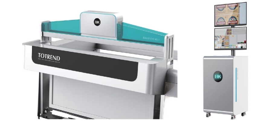
Digitalization is revolutionizing the printing and packaging industry, enhancing traditional processes and introducing new levels of efficiency and precision. A significant advancement in this context is the digitalization of print inspection, which is profoundly improving how print quality is monitored, controlled, and assured, resulting in superior output and reduced waste.
Key Components of Digital Print Inspection
Digital print inspection is a sophisticated process that leverages advanced technologies to ensure the highest quality in printed materials.
1. High-Resolution Cameras
Functionality:
Capture detailed images of printed materials at high speeds.
Detect minute defects that might be missed by the naked eye.
Features:
High Resolution: Enables detection of fine details and small defects.
Speed: Inspects large volumes of print quickly, suitable for high-speed printing processes.
Versatility: Adjustable to different types of printing substrates and conditions.
2. Image Processing Algorithms
Functionality:
Analyze images captured by the cameras in real-time.
Compare captured images against pre-defined standards or templates to identify defects.
Features:
Real-Time Analysis: Provides immediate feedback, allowing for quick corrections.
Defect Detection: Identifies various issues, including color variations, misregistrations, smudges, and surface imperfections.
Precision: Ensures high accuracy in identifying defects, minimizing false positives and negatives.
3. Artificial Intelligence (AI) and Machine Learning (ML)

Functionality:
Enhance inspection systems' capability to learn from past data and improve over time.
Predict potential issues and adapt to new types of defects.
Features:
Learning Capabilities: Systems improve accuracy and efficiency with use.
Predictive Analysis: Anticipates defects before they become significant problems.
Adaptive Algorithms: Adjusts to changing print conditions and defect types, maintaining high inspection standards.
4. Data Integration and Analytics
Functionality:
Integrate printing quality inspection systems with other digital tools and platforms for comprehensive data collection and analysis.
Provide insights into the printing process, helping optimize workflows and improve quality control.
Features:
Comprehensive Data Collection: Detailed data on every aspect of the print process.
Analytical Tools: Analyzes data trends, identifies recurring issues, and suggests improvements.
Real-Time Monitoring: Continuous monitoring and reporting facilitate proactive management of the print process.
5. User Interfaces and Software
Functionality:
Provide an interface for operators to interact with the inspection system, review defects, and manage settings.
Software platforms facilitate the setup, control, and analysis of the inspection process.
Features:
User-Friendly Interfaces: Intuitive interfaces for quick understanding and usage.
Customizability: Systems tailored to specific user needs and printing conditions.
Comprehensive Reporting: Detailed reports on inspection results aid decision-making and process improvements.
6. Lighting System
Functionality:
Provide consistent and appropriate lighting to ensure high-quality image capture by the cameras.
Different types of lighting can be used depending on the material and type of defects being inspected.
Features:
Uniform Illumination: Consistent lighting across the entire print area, avoiding shadows and glare.
Adjustable Lighting: Can be adjusted to suit different materials and inspection requirements.
Specialized Lighting: Techniques like UV or infrared lighting can highlight specific types of defects.
7. Motion Control Systems
Functionality:
Ensure precise movement and positioning of the print media under the inspection cameras.
Synchronize the inspection process with the printing process.
Features:
Precision: High accuracy in positioning, critical for detailed inspection.
Synchronization: Keeps the inspection process aligned with the speed and flow of the printing process.
Flexibility: Can handle different sizes and types of print media.
Challenges and Future Prospects in Digital Print Inspection
Challenges in Digital Print Inspection
High Initial Investment:
Cost Barrier: Advanced technology and equipment involve significant upfront costs, challenging for small to medium-sized printing companies.
Return on Investment (ROI): Justifying the ROI can be difficult if existing inspection methods are still acceptable.
Integration with Existing Systems:
Compatibility Issues: Integrating new digital inspection systems with legacy equipment and software can be complex, requiring significant modifications.
Operational Disruption: The integration process can disrupt ongoing operations, leading to downtime and temporary productivity losses.
Complexity and Usability:
Training Requirements: Advanced systems require specialized knowledge and skills, necessitating comprehensive training programs.
User Interface: Ensuring systems are user-friendly and intuitive is critical, as complex interfaces can hinder effective usage.
Data Management:
Volume of Data: Digital inspection systems generate large volumes of data, requiring effective management and analysis.
Data Security: Protecting sensitive production data from cyber threats requires robust cybersecurity measures.
Rapid Technological Advancements:
Keeping Up: Fast-paced technological advancements mean systems can quickly become outdated, necessitating continuous updates and investments.
Standardization: Lack of standardization in digital inspection technologies can lead to compatibility and interoperability issues.
Future Prospects in Digital Print Inspection
The future of digital print inspection is promising. Advancements in AI and machine learning will continue enhancing system capabilities, enabling more precise and efficient inspections. Integrating print inspection data with other Industry 4.0 technologies, such as the Internet of Things (IoT) and blockchain, could offer unprecedented levels of traceability and transparency.
Conclusion
The digitalization of print inspection represents a significant leap forward for the printing industry, offering numerous advantages in accuracy, efficiency, and cost-effectiveness. Digital print inspection plays an increasingly vital role in ensuring high standards of print quality, driving innovation, and maintaining competitiveness in a fast-paced market.
Set screws and headless screws are essential fasteners used to secure objects in place, but they differ significantly in design and application. The primary distinction lies in the presence or absence of a head, impacting their suitability for various uses.

Head
Set screws feature a head typically made from a harder material than the body of the screw, as it endures more wear and tear. The head can be slotted, hex, or square, providing versatility in applications.
Conversely, headless screws, also known as grub screws, usually have a socket head designed to be turned with a socket wrench or Allen wrench. Available in various sizes, socket heads offer flexibility for different applications.
Drive
The drive refers to the part of the screw used for turning. Set screws can have slotted, hex, or square drives, each with unique benefits. Slotted drives are common and easy to use with various tools. Hex drives offer more security and can be turned with a hex wrench, while square drives, though less common, provide maximum security and require a square wrench.
Headless screws also come with slotted, hex, or Allen drives, designed for efficient and secure fastening.
Application
Set screws are ideal for applications where the screw head needs to be flush with the object's surface, such as in electrical equipment or machinery where high torque is required.
Headless screws are suited for scenarios where the screw head needs to be concealed, like securing decorative objects or in automotive applications where they must withstand significant vibration.
Other Differences
Besides head and drive distinctions, material and threading also belong to the differences between set screws and headless screws. Set screws are generally made from harder materials to endure higher torque and are usually threaded along their entire length. In contrast, headless screws are often partially threaded.
Selecting the Right Screw
When choosing between set screws and headless screws, consider these factors:
Material Compatibility: Ensure the screw material is compatible with the object being secured to avoid issues like corrosion.
Size: Match the screw size to the hole size in the object for secure fastening without damage.
Drive Type: Select a drive type compatible with your available tools.
Application Needs: Use set screws if the head needs to be flush with the surface and headless screws if it needs to be hidden.

Additionally, consider:
Torque Rating: Choose a screw with an appropriate torque rating for the expected force.
Thread Pitch: A finer thread pitch provides a tighter grip but is harder to turn.
Length: Ensure the screw is long enough to secure the object without protruding excessively.
Conclusion
Set screws and headless screws both serve crucial roles in securing objects, with the main difference being the presence of a head. Selecting the appropriate type depends on the specific application requirements, ensuring optimal performance and durability.