As the global demand for energy continues to rise, oil exploration ventures increasingly turn to subsea technologies to unlock resources in challenging offshore environments. Subsea technologies are critical for enabling efficient oil exploration in deep waters, where traditional methods are often impractical. This article explores key subsea technologies, their impact on efficiency, and future advancements shaping the industry.

Key Subsea Technologies
1. Subsea Wellheads and Trees
Subsea wellheads and trees are essential for managing the flow of oil and gas from reservoirs located beneath the seabed. These systems provide pressure control, monitoring, and safe extraction.
Impact: Advanced subsea wellheads can withstand extreme pressures and temperatures, enabling exploration in deep and ultra-deep waters.
Example: Horizontal subsea trees are increasingly used for high-pressure, high-temperature (HPHT) wells, offering enhanced flexibility and reliability.
2. Subsea Umbilicals and Flowlines
Umbilicals and flowlines connect subsea equipment to surface facilities or shore-based infrastructure. They deliver power, control signals, and chemicals necessary for operation.
Impact: Advanced materials and designs reduce installation time and improve resistance to harsh subsea conditions.
Example: Electrically heated flowlines mitigate hydrate formation, ensuring uninterrupted flow in cold, deep-water environments.
3. Subsea Boosting Systems
These systems include subsea pumps and compressors that enhance production by reducing backpressure on wells.
Impact: Boosting systems extend the economic life of reservoirs by enabling the recovery of resources from low-pressure zones.
Example: Subsea multiphase pumps can handle a mixture of oil, gas, and water, eliminating the need for separation at the seabed.
4. Subsea Robotics and Autonomous Vehicles
Remotely Operated Vehicles (ROVs) and Autonomous Underwater Vehicles (AUVs) perform inspections, maintenance, and repairs on subsea equipment.
Impact: Robotics improve operational safety and reduce costs associated with human divers in hazardous conditions.
Example: Advanced AUVs equipped with machine learning capabilities can autonomously survey and map complex subsea environments.
5. Subsea Processing Systems
These include subsea separators, compressors, and water reinjection systems that process hydrocarbons directly at the seabed.
Impact: Subsea processing minimizes the need for extensive topside facilities, reducing costs and environmental impact.
Example: Subsea water separation systems reinject water back into the reservoir, reducing transportation costs and increasing oil recovery.

Benefits of Subsea Technologies
Enhanced Resource Recovery
Subsea technologies enable access to previously untapped or uneconomical reserves, particularly in deep and ultra-deep waters.
Improved Safety
By reducing reliance on surface infrastructure, subsea systems mitigate risks associated with severe weather and accidents.
Cost Efficiency
Innovations in subsea equipment and installation techniques lower exploration and production costs.
Environmental Impact Reduction
Compact subsea processing units and advanced flowline technologies reduce the ecological footprint of offshore oil exploration.
Challenges and Solutions
Harsh Environmental Conditions
Extreme pressures, temperatures, and corrosive environments pose challenges to subsea equipment.
Solution: High-performance materials like super duplex stainless steel and composite polymers improve durability.
Installation Complexity
Deploying subsea systems requires specialized vessels and precise coordination.
Solution: Modular designs and advanced installation tools streamline deployment processes.
Monitoring and Maintenance
The remote nature of subsea engineering systems complicates inspection and repair tasks.
Solution: Real-time monitoring systems and predictive maintenance strategies, powered by IoT and AI, enhance equipment reliability.

Future Trends
Digitalization and Automation
Integration of oil and gas simulation technologies, AI, and IoT enables real-time monitoring and optimization of subsea operations.
Energy Transition
Hybrid systems that support oil and gas production while enabling carbon capture and storage are gaining traction.
Subsea-to-Shore Solutions
Elimination of surface facilities through direct subsea-to-shore processing reduces costs and environmental impact.
Advanced Materials
Development of materials with higher resistance to fatigue and corrosion will expand the operational lifespan of subsea equipment.
Conclusion
Subsea technologies are transforming the oil exploration landscape, enabling efficient extraction of resources from challenging offshore environments. By addressing operational challenges through innovation, these technologies are poised to play a pivotal role in meeting global energy demands while minimizing environmental impact. Continued investment in research and development will drive the evolution of subsea solutions, ensuring their relevance in a rapidly changing energy sector.
Web guiding systems play a crucial role in various industries, ensuring the precise alignment and tracking of material webs during processing. However, managing wider webs introduces unique challenges that demand advanced solutions. Below, we explore the primary difficulties faced in web guiding for wider webs and potential strategies to overcome them.

Principles of Web Guiding
Web guide systems are designed to detect and correct misalignments of material webs as they travel through a processing line. The system typically comprises:
Sensors to monitor web edges, centerlines, or printed features.
Actuators to adjust the web's position in real time.
Controllers to process sensor data and command actuators.
In the case of wider webs, these components must be optimized to account for the larger width and associated challenges.

Challenges and Solutions in Web Guiding for Wider Webs
1. Increased Web Tension Variability
Wider webs are inherently more prone to tension inconsistencies across their width. Factors such as uneven material density, stretching, or external environmental conditions can cause localized tension imbalances. This variability can lead to wrinkling, misalignment, or even tearing of the web.
Solution: Advanced tension control systems with multiple sensors and actuators are necessary to monitor and adjust tension dynamically across the entire web width.
2. Challenges in Sensor Alignment
Accurately tracking the edges or centerline of a wider web requires highly precise sensor placement and calibration. Wider webs increase the likelihood of sensor blind spots or errors due to misalignment.
Solution: Using multiple high-resolution web guide sensors, including edge or line-following systems, can help ensure consistent tracking. Modern sensors equipped with machine learning capabilities can adapt to changing conditions and improve reliability.

3. Deflection and Sagging
As the web width increases, its weight and tension can cause deflection or sagging, particularly in the middle of the web. This deflection can interfere with the guiding system, leading to alignment issues.
Solution: Utilizing rollers with optimal diameter and material to support the web uniformly can reduce sagging. Additionally, air-floatation systems or vacuum hold-downs can be employed for lightweight materials.
4. Load Distribution on Guiding Mechanisms
Guiding mechanisms, such as steering rollers or pivoting frames, face greater mechanical loads with wider webs. These increased loads can lead to wear and tear, reducing the overall efficiency and accuracy of the system.
Solution: Employing reinforced guiding mechanisms and materials with high durability can mitigate wear. Regular maintenance schedules should be implemented to ensure consistent performance.
5. Limited Corrective Action Response Time
With wider webs, the time required to correct alignment errors increases due to the larger distance that needs adjustment. This delay can result in material wastage or process inefficiencies.
Solution: Implementing high-speed actuators and real-time control systems minimizes the corrective response time. Integrating predictive analytics can also help detect and address potential misalignment issues proactively.
6. Environmental Influences
Wider webs are more susceptible to external influences such as temperature variations, humidity, and airflow, which can impact material behavior and alignment.
Solution: Enclosing the web handling system in a controlled environment can minimize external disturbances. Monitoring and adjusting for environmental factors using sensors and automated controls ensure consistent operation.
7. Material Variability
Materials used for wider webs, such as laminates or composites, often exhibit inconsistent properties across their width. These variations can cause tracking issues during processing.
Solution: Conducting thorough material characterization before production and adjusting guiding system parameters for specific materials ensures better alignment. Adaptive systems capable of learning material behavior can further enhance reliability.
Applications of Wider Web Guiding
Printing Industry: Maintaining precise alignment for high-speed and wide-format printing.
Packaging: Ensuring accurate lamination and coating in flexible packaging applications.
Textile Manufacturing: Managing the variability and elasticity of wide fabric rolls.
Film Production: Maintaining alignment in wide plastic or composite films for industrial and consumer applications.
Conclusion
The challenges in web guiding for wider webs necessitate advanced, robust, and adaptive solutions. By addressing tension variability, sensor accuracy, deflection, and environmental factors, manufacturers can ensure precise web alignment and reduce material waste. As technology evolves, innovations in sensor technology, machine learning, and real-time control systems are poised to tackle these challenges, enabling more efficient and reliable web guiding for wider applications.
Marine searchlights play a vital role in ensuring safety and navigation, especially during night operations or adverse weather conditions. High-power searchlights are indispensable in illuminating vast areas, but their intense brightness often comes with a significant challenge: heat generation. Dissipating heat effectively in high-power marine searchlights is critical to maintaining performance, extending component lifespan, and ensuring safety.

The Challenge of Heat in High-power Searchlights
High-power marine searchlights use energy-intensive light sources like LED, halogen, or xenon lamps. These sources generate considerable heat as a byproduct of their operation. Without proper heat dissipation, marine searchlights can experience:
Reduced efficiency due to overheating.
Premature failure of internal components.
Structural damage to casings or reflectors.
Increased maintenance needs.
Marine environments compound these challenges with factors like high humidity, salt exposure, and limited ventilation.

Key Techniques for Effective Heat Dissipation
To overcome the challenges of heat management, manufacturers employ a combination of innovative designs and advanced materials. Below are some proven techniques:
1. Enhanced Heat Sinks
Heat sinks, often crafted from aluminum or copper, play a crucial role in transferring heat away from the light source. Enhanced designs with optimized fin geometry increase surface area, promoting faster cooling through convection.
2. Active Cooling Systems
Active cooling systems, such as small integrated fans, circulate air within the searchlight housing. These systems are particularly beneficial for high-power applications requiring extended operation.
3. Liquid Cooling Technology
For extreme heat scenarios, liquid cooling systems offer a robust solution. Coolant absorbs heat from critical components and transfers it to an external radiator, ensuring consistent operation even in demanding conditions.
4. Thermal Interface Materials (TIMs)
Modern marine searchlights utilize TIMs to enhance heat conduction between components. These materials reduce thermal resistance, allowing for efficient heat transfer to the heat sink or cooling system.
5. Ventilation and Housing Design
Innovative housing designs integrate venting mechanisms while maintaining waterproof and dustproof standards. Materials such as corrosion-resistant alloys and thermoplastics with high thermal stability ensure durability and efficient heat management.
Addressing Marine-specific Challenges
Heat dissipation solutions must meet the unique demands of marine environments:
Waterproofing: Active cooling mechanisms, such as fans or vents, must be carefully designed to maintain waterproof integrity (e.g., achieving IP66 or higher ratings).
Corrosion Resistance: Heat dissipation materials must withstand saltwater and humidity to prevent degradation over time.
Shock and Vibration Resistance: Ships are subject to constant motion, requiring robust and secure cooling components.
Innovative Solutions in Heat Management
Recent advancements in searchlight technology focus on incorporating intelligent thermal management systems. These systems include temperature sensors that dynamically adjust fan speeds or light intensity to prevent overheating.
LED technology has further revolutionized heat management. LED marine searchlights are more energy-efficient and produce less heat compared to traditional search lights with halogen or xenon lamps, reducing the burden on cooling systems.

Future Directions in Heat Dissipation
As marine operations evolve, the demand for more efficient and sustainable solutions grows. Future advancements may include:
Nano-coatings to enhance heat transfer and corrosion resistance.
Phase-change materials to absorb and dissipate heat efficiently.
AI-driven thermal management systems that optimize cooling based on real-time conditions.
In conclusion, dissipating heat effectively in high-power marine searchlights is crucial for reliable and safe operation. Advanced cooling techniques, innovative materials, and intelligent systems ensure these searchlights perform optimally in demanding environments. By addressing thermal challenges head-on, manufacturers continue to enhance the resilience and functionality of marine searchlights, paving the way for safer and more efficient marine operations.
U bolts are essential fasteners widely used in various industries, including construction, automotive, and marine applications. They are shaped like the letter "U," with threaded ends, and are designed to secure pipes, rods, or other cylindrical objects to surfaces. Accurate measurement of U-bolts is crucial for ensuring a proper fit and optimal performance. This guide delves into the intricacies of measuring U-bolts accurately, covering their structure, applications, and step-by-step procedures for precise measurement.

Understanding U-Bolts
Structure of a U-Bolt
A typical U-bolt consists of the following components:
Bend or Curve: The curved portion forms the "U" shape, designed to wrap around cylindrical objects.
Legs or Arms: These are the two parallel threaded ends extending from the curve.
Threads: The lower part of the legs is threaded to accommodate nuts for fastening.
Plate (Optional): Some U-bolts include a plate that helps distribute load evenly when the bolt is tightened.
Applications of U-Bolts
A U bolt serve diverse functions, such as:
Securing Pipes: Commonly used to anchor pipes in plumbing and mechanical systems.
Automotive Uses: Often employed to attach leaf springs, exhaust systems, or stabilizers.
Marine Applications: Used for securing rigging, poles, and structural supports.
Construction: Essential in assembling frameworks or scaffolding.

Why Accurate Measurement Matters
Ensuring Proper Fit
Accurate measurements prevent mismatches that can lead to poor installation, reduced efficiency, or even structural failure.
Maintaining Load Distribution
Precise dimensions ensure the U-bolt evenly distributes loads, minimizing stress on the fastened object.
Enhancing Safety
Incorrectly sized U-bolts can compromise the integrity of the assembly, posing safety risks.
Key Dimensions of U-Bolts to Measure
When measuring U-bolts, focus on the following dimensions:
Inside Width: The distance between the inner sides of the legs, measured at the curve.
Inside Height: The distance from the inside of the curve to the end of the legs.
Diameter of the Bolt: The thickness of the legs, typically measured as the outer diameter of the bolt.
Length of Threads: The length of the threaded portion of the legs.
Bend Radius: The curvature of the "U," measured from the center of the bend to the midpoint of the legs.
Tools Needed for Measuring U-Bolts
To ensure accurate measurements, use the following tools:
Calipers: Ideal for measuring the diameter and thread length.
Measuring Tape or Ruler: Used for determining the inside width and height.
Thread Gauge: Helps verify the thread pitch and size.
Protractor (Optional): Useful for assessing the bend radius if required.
Step-by-Step Guide to Measuring U-Bolts
1. Measure the Inside Width
Place the U-bolt on a flat surface.
Use a ruler or calipers to measure the distance between the inner sides of the legs at the widest point.
Record the measurement in millimeters or inches, depending on your preference.
2. Determine the Inside Height
Measure from the inside of the curve (at its apex) to the end of the legs.
Ensure the measuring tool is perpendicular to the surface for accurate results.
3. Measure the Bolt Diameter
Use calipers to measure the outer diameter of the legs.
Ensure the calipers are snug but not overly tight for an accurate reading.
4. Assess the Thread Length
Measure the length of the threaded portion of the legs using a ruler or calipers.
Confirm the thread type and pitch with a thread gauge.
5. Check the Bend Radius (Optional)
For specialized applications, use a protractor or template to determine the bend radius.
Place the U-bolt over the template and align it to find the radius.
6. Record and Verify Measurements
Double-check all dimensions to ensure accuracy.
Compare the measurements against the specifications required for your application.
Tips for Accurate Measurement
Use Appropriate Tools: Always use calibrated tools to ensure precision.
Handle U-Bolts Properly: Avoid bending or distorting the bolt during measurement.
Take Multiple Readings: Measure each dimension more than once to confirm consistency.
Measure at Room Temperature: Temperature changes can slightly affect the dimensions of metal U-bolts.
Common Challenges and Solutions
Challenge 1: Inconsistent Measurements
Solution: Ensure the measuring tool is correctly aligned and the U-bolt is not tilted or skewed.
Challenge 2: Difficulty Measuring Threads
Solution: Use a thread gauge to determine thread pitch and verify thread length with a ruler.
Challenge 3: Measuring Odd-Shaped U-Bolts
Solution: For custom or non-standard U-bolts, take additional measurements and consult the specifications from the bolt manufacturer.

Selecting the Right U-Bolt
When purchasing U-bolts, consider the following factors:
Material: Choose a material suitable for the application, such as stainless steel for corrosion resistance or carbon steel for high strength.
Coating: Galvanized or zinc-plated U-bolts offer additional protection against rust.
Load Capacity: Ensure the U-bolt can withstand the expected load without deformation.
Standards Compliance: Verify that the U-bolt meets industry standards (e.g., ASTM, DIN) for quality and performance.
Maintaining and Inspecting U-Bolts
Regular Inspection: Check for signs of wear, corrosion, or deformation.
Proper Torqueing: Avoid over-tightening, which can weaken the threads or distort the U-bolt.
Lubrication: Apply anti-corrosion coatings or lubricants for U-bolts exposed to harsh environments.
Conclusion
Accurately measuring U-bolts is a critical step in ensuring proper fit, safety, and performance across various applications. By understanding their structure, dimensions, and measurement techniques, you can select and install the right U-bolts with confidence. Armed with the right tools and a methodical approach, you can achieve precision and reliability in your projects.
Investing time in accurate measurements not only saves money but also prevents potential failures, making it an indispensable practice for engineers, technicians, and DIY enthusiasts alike.
In laboratory workflows, the importance of using the right equipment cannot be overstated. Among the various tools available, vortex mixers and centrifuges are two indispensable devices, each serving unique purposes. Although both involve the manipulation of liquids in containers, their operational principles, applications, and benefits are entirely different. This article delves into the intricacies of vortex mixers and centrifuges, offering insights into their roles, features, and ideal applications to help you make an informed choice.

Understanding Vortex Mixers
What is a Vortex Mixer?
A vortex mixer is a compact, motor-driven device designed to mix liquids in tubes or small containers by creating a vortex. This action ensures homogeneity in the sample, making it an essential tool for various laboratory tasks that require quick and efficient mixing.
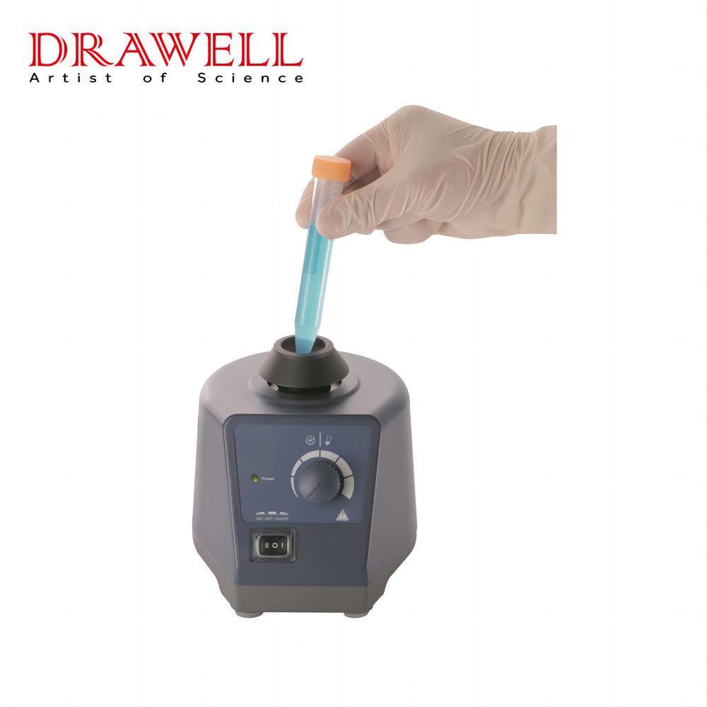
How Does It Work?
The vortex mixer has a motor attached to a rubber cup or platform.
When a tube is pressed against the platform, the motor causes the liquid inside the container to move in a circular motion, forming a vortex.
Depending on the model, the device can operate in touch-activated mode or continuous mode.
Key Applications of Vortex Mixers
Mixing Reagents: Ideal for preparing chemical solutions and reagents quickly and effectively.
Resuspending Cells: Frequently used in microbiology and molecular biology to resuspend cells or pellets in culture media.
Homogenization: Effective for homogenizing liquids prior to downstream analysis or processing.
General Mixing: Suitable for blending components in small tubes, vials, or microplates.
Understanding Centrifuges
What is a Centrifuge?
A centrifuge is a laboratory device used to separate components of a mixture based on density. By spinning samples at high speeds, it applies centrifugal force, causing denser materials to settle at the bottom while less dense materials remain at the top.

How Does It Work?
Samples are loaded into tubes and placed in a rotor inside the centrifuge.
As the rotor spins, centrifugal force acts on the sample.
This force pushes denser particles outward (toward the bottom of the tube) while lighter components form a supernatant layer above.
Key Applications of Centrifuges
Blood Fractionation: Separating plasma, serum, or blood cells for diagnostic or research purposes.
Protein and Nucleic Acid Purification: Essential for molecular biology techniques, including isolating DNA, RNA, and proteins.
Cell Harvesting: Used to collect and concentrate cells from culture media.
Industrial Applications: Used in pharmaceutical manufacturing, food processing, and waste treatment.
Comparing Mechanisms and Functionality
Mixing vs. Separation
The fundamental difference between a vortex mixer and a centrifuge lies in their purpose. A vortex mixer is designed to mix liquids, ensuring uniformity, while a centrifuge is used to separate components within a liquid mixture based on their densities.
Speed and Force
Vortex Mixers: Operate at lower speeds (2,500–3,000 RPM) suitable for gentle mixing.
Centrifuges: Operate at significantly higher speeds (10,000–100,000 RPM for ultracentrifuges) to generate the high centrifugal forces required for separation.
Operational Modes
Vortex Mixers: Simple to use, with touch-activated or continuous operation modes.
Centrifuges: Require programming of speed, time, and sometimes temperature, depending on the complexity of the model.
Advantages and Limitations
Vortex Mixers
Advantages:
Compact and affordable.
Easy to operate and maintain.
Quick and efficient for small-scale mixing tasks.
Limitations:
Limited to mixing and cannot separate components.
Unsuitable for large volumes or complex mixing requirements.
Centrifuges
Advantages:
Capable of high-precision separation.
Versatile, with applications ranging from research to industrial processes.
Advanced models include temperature control and vacuum features for sensitive samples.
Limitations:
Expensive and requires more maintenance.
Bulky and space-consuming.
Longer setup and operation time compared to vortex mixers.
Practical Considerations for Selection
When choosing between a vortex mixer and a centrifuge, it is important to consider the specific needs of your application:
Nature of the Task:
For simple mixing of liquids or resuspension tasks, a vortex mixer is ideal.
For separating components or isolating substances, a centrifuge is essential.
Sample Volume:
Vortex mixers are suitable for small volumes in tubes or microplates.
Centrifuges can handle a wide range of volumes, from microcentrifuge tubes to large industrial-scale containers.
Precision Requirements:
Vortex mixers provide uniform mixing but lack precision control.
Centrifuges allow precise control over speed, time, and temperature for accurate separations.
Budget and Space:
Vortex mixers are cost-effective and compact, making them ideal for small labs.
Centrifuges are more expensive and require dedicated space, especially high-capacity models.
Real-World Scenarios
Scenario 1: Molecular Biology Research
In a molecular biology lab, both devices may be used in tandem. A vortex mixer is used to resuspend DNA or RNA in buffer solutions, while a centrifuge is utilized for isolating and purifying these nucleic acids.
Scenario 2: Clinical Diagnostics
In clinical settings, centrifuges are critical for blood fractionation, while vortex mixers assist in preparing reagent mixtures for diagnostic assays.
Scenario 3: Pharmaceutical Industry
Pharmaceutical labs frequently employ centrifuges for drug formulation and quality testing. Vortex mixers, on the other hand, are used for preparing chemical solutions during research and development.
Emerging Trends and Innovations
Vortex Mixers:
Advanced models with digital controls and multiple attachments for increased versatility.
Integration with automation systems for high-throughput workflows.
Centrifuges:
Development of ultracentrifuges capable of higher speeds and precision.
Energy-efficient designs with reduced noise and heat generation.
Enhanced safety features, such as imbalance detection and automatic shut-off systems.
Conclusion
Vortex mixers and centrifuges are foundational tools in laboratories worldwide, each excelling in their respective domains. While vortex mixers are perfect for quick, efficient mixing tasks, centrifuges are indispensable for precise separations. Understanding their differences and applications allows for optimal use, ensuring that laboratory operations are efficient, accurate, and aligned with experimental goals.
Whether you’re managing a small research lab or a large industrial facility, the choice between these two devices ultimately depends on your specific needs. By selecting the right tool for the job, you can enhance productivity and achieve superior results in your work.